


+86 13603063656
2 Layer PCB Explained: Benefits, Applications & Complete Guide. That’s what you’re here for—and you’re in the right place. In the world of electronics manufacturing, understanding the ins and outs of a 2 layer PCB isn’t just useful; it’s essential for decision-makers, engineers, and procurement specialists alike. Why? Because the 2 layer PCB is the quiet powerhouse behind countless products, balancing complexity with cost-efficiency. But here’s the real story: while it seems simple, mastering 2 layer PCB design and production can elevate your business and boost your bottom line. This article delivers a full-scope, B2B-focused guide—from structure, advantages, and manufacturing to applications, troubleshooting, and supplier selection. Ready for the good part? Let’s peel back the layers—literally—and discover everything you need to know to make the best choices for your projects.

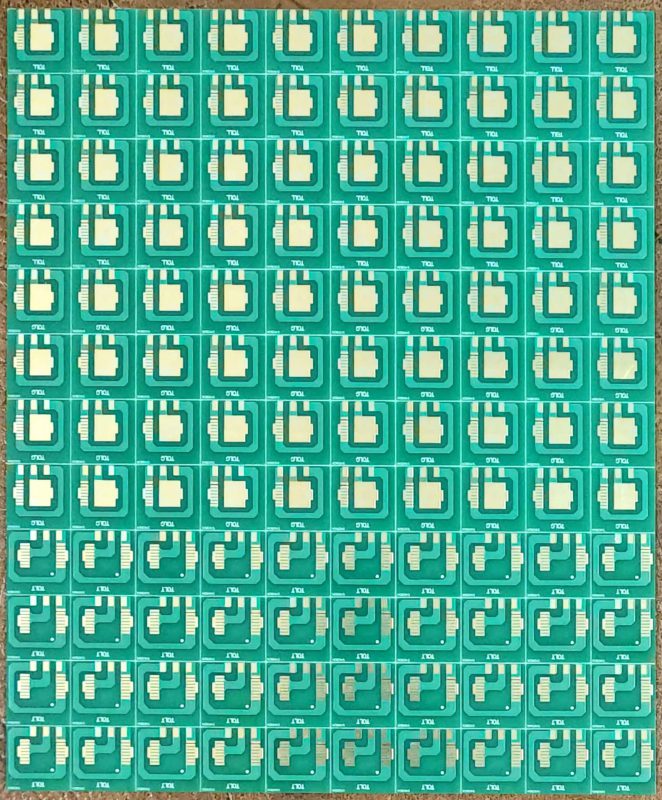
2 Layer PCB
The key structure of a 2 layer PCB is deceptively simple yet remarkably powerful. At its core, a 2 layer PCB consists of a non-conductive substrate—usually FR4—sandwiched between two copper layers, one on each side. This dual-layer approach doubles the real estate for routing signals, enabling more complex designs than single-sided boards. But what’s the kicker? It achieves this without the high cost and technical demands of multilayer PCBs.
The copper layers are etched to form intricate traces, each acting as a microscopic highway for electricity. Vias—tiny holes plated with copper—connect the top and bottom layers, allowing signals to travel vertically. On top of the copper, you’ll find a solder mask, which insulates the traces and prevents solder bridges. The silkscreen layer comes last, providing component outlines, part numbers, and orientation guides.
Let’s talk examples: A consumer audio amplifier might use a 2 layer PCB to separate power and signal traces, minimizing noise. Industrial controls often rely on the increased density of 2 layer PCBs for compact relays and logic modules. And in the LED lighting world, the structure supports thermal management while maximizing layout flexibility. The bottom line? Every feature of the 2 layer PCB’s structure is engineered for reliable, scalable production.
| Layer | Material | Function | Example |
|---|---|---|---|
| Top Copper | Copper | Signal/Power Routing | Power traces, signal paths |
| Substrate | FR4, CEM-1 | Insulation, Mechanical | Structure, durability |
| Bottom Copper | Copper | Signal/Power Routing | Ground plane, LED wiring |
| Solder Mask | Epoxy, Green/Red/Blue | Insulation, Protection | Prevents shorts |
| Silkscreen | Ink | Markings, Labels | Component IDs, logos |
Now, let’s dive deeper: how does a 2 layer PCB actually work? The answer starts with the dual-sided copper layers. Each side is home to its own network of traces, and thanks to vias—plated holes—you can jump signals from one layer to another, effectively weaving a 3D circuit within a flat board. But here’s where it gets interesting: this arrangement slashes the number of crossovers and complex jumpers, making design cleaner and assembly faster.
Component mounting is equally flexible. Both surface mount devices (SMD) and through-hole components can be used, with SMDs on one or both sides for high-density needs. Ground planes and power rails can be strategically placed, enhancing noise immunity and signal integrity—crucial in applications like analog audio, motor controllers, or IoT gateways.
Consider the following examples. A home automation hub employs a 2 layer PCB to distribute both logic signals and power without cross-talk. An industrial sensor controller uses both sides for analog and digital separation. And a startup’s rapid prototype leverages the dual layers for last-minute routing fixes.
Ready for the good part? This dual-layer approach gives engineers more design freedom while controlling costs and complexity—a sweet spot for countless applications.
| Function | Feature | Example Use |
|---|---|---|
| Signal Routing | Two-sided copper | Mixed-signal designs |
| Vertical Connections | Vias | Power to ground |
| Component Mounting | SMD & THT | Flexibility in assembly |
| Power Distribution | Dedicated planes | Motor drivers |
| Grounding | Noise reduction | Audio PCBs |
So, what’s the real story behind the popularity of 2 layer PCBs? Let’s break down the main advantages. First, cost-effectiveness: a 2 layer PCB is far less expensive than its multilayer cousin but packs a lot more punch than a single-sided board. This makes it the go-to for medium-complexity products.
But here’s the kicker—2 layer PCBs offer improved routing options. More real estate for traces means easier design for engineers, fewer jumper wires, and greater reliability. Versatility comes next: from industrial automation to smart lighting and consumer gadgets, a 2 layer PCB adapts to a huge range of applications.
Want real-world proof? A wearable device manufacturer switched from single-sided to 2 layer PCBs and halved their assembly defects. An automotive LED module project used dual layers to keep circuits compact while handling higher currents. And an IoT company cut costs by 30% compared to 4 layer alternatives, without sacrificing function.
Bottom line: if you need a balance of complexity, performance, and price, the 2 layer PCB is a hard act to beat.
| Advantage | Benefit | Example |
|---|---|---|
| Cost-effective | Lower BOM & assembly cost | Smart home devices |
| Design flexibility | More routing space | Sensors, relays |
| Higher density | More components per cm² | LED controllers |
| Simpler manufacturing | Shorter lead times | Consumer goods |
But let’s not get ahead of ourselves. While the 2 layer PCB has plenty of strengths, it’s not without limitations. First up: design constraints. With only two copper layers, there’s less room for complex routing compared to four, six, or eight layer boards. What’s the real story? As circuit complexity grows—think microprocessor boards or dense FPGAs—2 layer designs quickly hit a wall.
Signal interference and electromagnetic compatibility (EMC) can also pose challenges. Traces on opposite sides can couple signals, causing unwanted noise if not carefully managed. And while 2 layer boards beat single-sided in terms of density, they simply can’t match multilayer designs when it comes to miniaturization or RF shielding.
For example, a high-frequency communication device might suffer from signal integrity issues on a 2 layer PCB. A robotics startup needed to upgrade to 4 layers to support high-speed data lines. And an automotive powertrain control module moved to multilayer boards to reduce size and improve heat dissipation.
But here’s the kicker: for low- to mid-complexity projects, these limitations are manageable. The key is knowing when to use a 2 layer PCB—and when to move up the technology ladder.
| Limitation | Impact | Typical Solution |
|---|---|---|
| Routing constraints | More jumpers/complexity | Optimize layout, move to multilayer |
| Signal interference | Noise, EMI | Careful trace planning, shielding |
| Size restrictions | Larger board area | Layer increase, advanced materials |
| Complexity cap | Limited circuits | Consider 4+ layer PCB |
Let’s look at the big picture. Where do 2 layer PCBs truly shine? Their adaptability opens doors in countless industries. In consumer electronics, you’ll find them in everything from smart thermostats to wireless speakers. Why? Because they balance features and cost, making mass production viable.
In industrial controls, 2 layer PCBs underpin PLC modules, relay boards, and sensor interfaces, where reliability is critical but extreme density isn’t necessary. Automotive lighting modules leverage 2 layer PCBs for compactness and efficient thermal management, powering LEDs and control circuits. And in the world of LED lighting, these boards manage both power distribution and signal routing, often in tough environments.
But here’s where it gets interesting: medical device startups often prototype on 2 layer boards for speed and cost, while keeping an upgrade path open for multilayer as designs mature. Smart agriculture and IoT developers love 2 layer PCBs for rapid prototyping and scalable manufacturing.
Consider these examples: A European LED luminaire company slashed time-to-market with standard 2 layer PCBs. An industrial machinery supplier reduced downtime with robust, repairable boards. And a consumer electronics giant uses 2 layer PCBs in wireless chargers for efficiency and durability.
| Application | Product Type | Key Benefit |
|---|---|---|
| Consumer Electronics | Smart home, audio | Cost, flexibility |
| Industrial Controls | PLC, sensors | Reliability, repairability |
| Automotive | LED modules | Heat management, size |
| IoT/Smart Tech | Gateways, sensors | Fast prototyping |
Designing a 2 layer PCB? There’s more to it than meets the eye. The process begins with schematic capture—mapping out your circuit in EDA software. Next comes the layout, where components are placed for optimal signal flow and minimum interference. But here’s the real story: routing traces is both art and science.
For a robust 2 layer PCB, maintain adequate trace width and spacing to handle current and avoid shorts. Industry standards (like IPC-2221) provide clear minimums, but savvy engineers often go above and beyond for reliability. EMI and crosstalk? Avoid parallel signal traces for long distances and use ground planes or fill where possible.
Case in point: An automation company used wider traces and separate analog/digital sections, slashing EMI issues in their control boards. A medical device startup minimized layout errors with color-coded netlists. And a solar inverter maker improved yield by standardizing DRC (design rule check) reviews before fabrication.
Ready for the good part? With the right design practices, your 2 layer PCB will meet performance targets and minimize costly rework.
| Guideline | Purpose | Recommendation |
|---|---|---|
| Trace width/spacing | Current handling, safety | 0.2mm+ for power, 0.15mm+ for signals |
| Layer stackup | Signal separation | Top: signals/power, Bottom: ground/signals |
| EMI/crosstalk | Noise reduction | Ground fill, short parallel traces |
| DRC checks | Catch errors early | Use EDA tool automation |
So, how is a 2 layer PCB brought to life? The manufacturing process is a blend of science and precision. It starts with the image transfer—using UV light to project the board’s pattern onto copper-clad laminate. Etching follows, removing unwanted copper and leaving behind intricate traces.
Next comes drilling: precision machines create holes for vias and component leads. Electroplating lines these holes with copper, creating electrical bridges between layers. But here’s the kicker: even the smallest misalignment at this stage can mean a failed batch, so manufacturers rely on strict process control and AOI (Automated Optical Inspection).
Solder mask application comes next, insulating the traces and prepping the board for assembly. The final touch? Silkscreen printing for part IDs and component orientation. Some boards receive special finishes—like HASL or ENIG—for improved solderability and corrosion resistance.
Real-world cases? A power supply OEM reduced defects by 70% after automating AOI during drilling and imaging. An LED manufacturer improved board lifespan with ENIG finish. And a control panel supplier used step-and-repeat image transfer to boost throughput.
| Step | Description | Key Equipment |
|---|---|---|
| Image Transfer | UV exposure, patterning | Photoplotter, laminator |
| Etching | Copper removal | Etching tanks |
| Drilling | Via/component holes | CNC drill |
| Plating | Copper deposit | Electroplating line |
| Solder Mask | Protective coating | Spray coater |
| Silkscreen | Markings | Screen printer |
Assembly is where the 2 layer PCB truly comes alive. The choice between Surface Mount Technology (SMT) and Through-Hole Technology (THT) impacts everything from production speed to reliability. SMT places components directly onto pads, supporting high-density designs and automation. THT, meanwhile, uses leads inserted through holes—ideal for larger, high-stress components.
But what’s the real story? Most modern assembly lines combine both methods, placing surface-mount chips and resistors on one side, with connectors or relays through-hole on the other. Manual assembly is common for prototypes and small runs, but for volume production, automation reigns supreme.
Quality assurance can’t be overlooked. AOI inspects solder joints and component placement, while ICT (In-Circuit Test) checks functionality. For critical products—like automotive safety modules—X-ray inspection validates hidden joints under large chips.
Case examples: A smart meter manufacturer cut production time in half using full SMT automation. An industrial relay supplier kept costs low with hybrid assembly. And a telecom hardware startup improved first-pass yield from 75% to 98% by introducing AOI post-assembly.
| Assembly Method | Use Case | Benefit |
|---|---|---|
| SMT | High volume, dense boards | Fast, automated, small parts |
| THT | Power, connectors | Strong, durable, larger parts |
| Hybrid | Mixed designs | Flexibility, performance |
| Manual | Prototypes, small runs | Customization, lower NRE |
Material selection is where engineering meets economics. FR4 is the industry standard for its reliability, cost, and insulation properties. But what’s the kicker? Specialty materials like CEM-1 offer alternatives for specific needs—think low-cost consumer electronics.
Copper thickness also matters: standard is 1oz/ft², but heavier copper (2oz or 3oz) is chosen for power boards or high-current circuits. The surface finish is the final touch, with HASL being cost-effective for most applications, while ENIG offers superior solderability and corrosion protection—vital for automotive, aerospace, and industrial markets.
Case studies: An LED signage supplier improved thermal performance by switching to 2oz copper. A portable medical device manufacturer reduced board failures using ENIG finish. And a toy maker reduced costs by opting for CEM-1 on low-risk products.
Environmental standards are also gaining ground—RoHS-compliant laminates are now the norm for export markets, supporting global compliance and sustainability goals.
| Material | Use | Advantage |
|---|---|---|
| FR4 | General, industrial | Reliable, affordable |
| CEM-1 | Low-cost, single-use | Cost savings |
| 1oz Copper | Standard electronics | Good balance |
| 2oz/3oz Copper | High power | More current |
| HASL | Mass production | Cost-effective |
| ENIG | High reliability | Solderability, longevity |
Ready for the good part? Cost optimization is always on the mind in B2B projects. The cost of a 2 layer PCB hinges on three big drivers: materials, process complexity, and volume. Material selection—FR4 vs. specialty laminates, copper thickness, and finish—can swing pricing by 30% or more.
Order quantity is another big one. Prototyping a handful of boards may cost $10 each, but with 10,000 units, the price can drop below $1 per board. Turnaround time also affects price—fast-track production commands a premium, but for time-to-market-sensitive projects, it can be a worthy investment.
Manufacturing complexity adds cost as well. Tighter tolerances, small via sizes, or specialized testing (like X-ray inspection) all increase NRE (Non-Recurring Engineering) fees.
Examples: A consumer wearable brand cut per-unit costs by 40% through volume orders. An industrial supplier paid more for rush orders but landed a key client. And an export firm improved margins by choosing local manufacturing to save on shipping and tariffs.
| Cost Factor | Impact | Strategy |
|---|---|---|
| Material Choice | Up to 30% | Select for needs, not over-spec |
| Quantity | High volumes = low cost | Batch ordering |
| Turnaround | Premium for speed | Plan for lead times |
| Special Features | NRE fees | Limit extras for prototypes |
In the world of 2 layer PCBs, quality is non-negotiable. IPC standards (like IPC-A-600) set the benchmark for board acceptability, while UL certification is vital for fire safety and market access in North America. But here’s the real story: quality assurance isn’t just about passing tests—it’s about process control from design to final inspection.
Testing starts with E-test (electrical test) to catch opens and shorts, then moves to AOI and functional tests as needed. For high-reliability sectors—think medical or automotive—traceability is built into every board, linking serial numbers to production batches and test results.
Consider these examples: A medical device OEM slashed field failures by mandating 100% AOI and UL-certified boards. An industrial firm cut warranty claims by 60% after implementing rigorous ICT. And a telecom supplier improved market access in the EU by meeting RoHS and CE requirements.
The implication? Quality standards and thorough testing are the foundation of customer trust, brand reputation, and global competitiveness.
| Standard/Test | Purpose | Who Requires It |
|---|---|---|
| IPC-A-600 | Acceptance criteria | All markets |
| UL Certification | Fire/electrical safety | US, Canada |
| E-Test | Open/short detection | Every board |
| AOI | Visual inspection | High volume |
| Traceability | Batch control | Medical, automotive |
But what if things go wrong? Every seasoned engineer knows: even with the best design, issues can arise. Typical faults in 2 layer PCBs include shorts (unintended copper bridges), opens (broken traces), and misalignments between layers or vias. But here’s the kicker: most faults are preventable with strong process control and quality checks.
Inspection starts with visual checks, followed by AOI, E-test, or even X-ray for stubborn problems. Repair options include micro-soldering, trace jumpers, or replacing components. For critical batches, a root-cause analysis traces faults to the source—be it material, process, or design.
Examples? A batch of LED drivers was saved by quick rework on via misalignments. An industrial relay board’s solder short was caught by AOI and fixed before shipping. And a consumer electronics brand implemented a “no fault forward” process—catching 99% of defects before assembly.
What’s the real story? Early detection and continuous improvement are the hallmarks of successful B2B PCB projects.
| Common Issue | Cause | Solution |
|---|---|---|
| Shorts | Solder bridges, mis-etch | AOI, rework |
| Opens | Broken traces | Solder jumpers |
| Misalignment | Process error | Tight process control |
| Component Fault | Handling, part quality | Incoming inspection |
Let’s take a peek into the future. Innovation isn’t reserved for multilayer boards—2 layer PCB technology is evolving too. Eco-friendly materials are entering the market, driven by regulatory and customer demand. Lead-free laminates, halogen-free solder masks, and recyclable substrates are no longer rare.
Advances in miniaturization are pushing the boundaries—tighter traces, smaller vias, and finer pitches make it possible to pack more into a 2 layer board than ever before. Digital tools like AI-driven design software speed up prototyping and catch errors early. Some suppliers now offer quick-turn 3D-printed PCB prototypes for rapid iteration.
Examples abound: An IoT startup leveraged AI-powered layout for faster design cycles. An automotive lighting brand met new EU green standards with recyclable boards. And a medical device innovator used rapid-prototype 2 layer PCBs to get to clinical trials in record time.
Ready for the good part? These trends mean greater flexibility, sustainability, and speed—putting your products ahead of the curve.
| Trend | Benefit | Example |
|---|---|---|
| Eco-Friendly | Compliance, branding | EU exports |
| Miniaturization | Higher density | Wearables |
| Digital Design | Fewer errors, speed | Startups |
| Rapid Prototyping | Fast to market | Medical devices |
The last mile matters most: choosing the right 2 layer PCB supplier can make or break your project. Start by evaluating manufacturing capabilities—look for up-to-date equipment, certifications (like IPC, UL), and sample quality. Next, assess quality control: does the supplier offer traceability, AOI, and clear inspection records?
Customer support is equally vital. Responsive communication, engineering support, and after-sales service all set leading suppliers apart. Don’t be shy—ask about previous projects, defect rates, and lead times. And here’s the real story: building a strong partnership can unlock better pricing, priority service, and technical insight.
Real-world examples? A robotics firm sped up development by partnering with a supplier offering on-site engineering consults. An automotive Tier 1 reduced defects with a supplier committed to continuous improvement. And a telecom startup cut supply risk by qualifying two certified vendors for backup.
The implications are clear: do your homework, build relationships, and treat your supplier as a partner, not just a vendor.
| Supplier Factor | Why It Matters | Pro Tip |
|---|---|---|
| Capability | Complex designs, fast lead | Visit facility, request samples |
| Certification | Compliance, access | Demand up-to-date docs |
| QC Process | Fewer defects | Ask for AOI/test reports |
| Support | Easier troubleshooting | Test their responsiveness |
In summary, the 2 layer PCB stands as a cornerstone of the electronics industry—balancing cost, complexity, and capability. From structure and manufacturing to troubleshooting and future trends, this guide has armed you with practical knowledge and strategic insights for your next project. The main finding? When chosen and executed wisely, a 2 layer PCB delivers robust performance and impressive value across countless applications. Ready to optimize your supply chain, innovate with confidence, and keep quality high? Choose your 2 layer PCB partners and processes carefully—and let your projects shine.
Q1: What is a 2 layer PCB?
A 2 layer PCB is a printed circuit board with two copper layers, enabling more complex circuits than single-sided boards.
Q2: How does a 2 layer PCB work?
It works by routing electrical signals through copper traces on both sides of the board, with vias connecting the two layers.
Q3: What are the main benefits of using a 2 layer PCB?
2 layer PCBs offer better routing, increased component density, and cost efficiency for moderate-complexity projects.
Q4: Where are 2 layer PCBs commonly used?
They are found in consumer electronics, automotive devices, industrial controls, and LED lighting.
Q5: What factors affect the cost of a 2 layer PCB?
Key factors include material choice, board size, order quantity, turnaround time, and chosen surface finish.


Connect to a Jerico Multilayer PCB engineer to support your project!
Request A Quote


 Quote
Quote