2025-03-11
218
PCB Capabilities: Key Features You Need to Know Before Ordering
Imagine this: You’ve meticulously designed a PCB, ensuring every layer, trace, and via aligns perfectly with your requirements. Confidently, you send your design for manufacturing, expecting flawless execution. But when the final product arrives, reality strikes hard—signal integrity is compromised, impedance is off, and some solder pads fail to connect properly. Worst of all, your production timeline is delayed, leading to increased costs and frustration.
What went wrong? A lack of understanding of PCB capabilities before placing the order.
A PCB is more than just a circuit board; it determines the stability, performance, and reliability of your entire electronic device. Understanding the key capabilities of a PCB before manufacturing ensures that your design translates seamlessly into a high-quality product, preventing costly errors and production failures.

PCB Capabilities
Understanding PCB Core Capabilities
Layer Count and Its Impact
-
Single-layer, double-layer, and multilayer PCB applications
- Single-layer PCBs are suitable for low-cost, simple electronics.
- Double-layer PCBs offer greater circuit integration for consumer electronics.
- Multilayer PCBs enable complex circuits and high-speed signal transmission, commonly used in industrial, medical, and communication applications.
-
How layer count affects signal integrity, heat dissipation, and manufacturing cost
- More layers allow for denser circuit integration but increase production costs.
- The symmetry and stacking method of layers directly impact EMI performance and signal quality.
Manufacturable PCB Size Range
- Maximum and minimum sizes
- The manufacturable maximum PCB size varies by factory, commonly reaching 600mm × 1200mm.
- The minimum size can be as small as 10mm × 10mm, ideal for compact electronic devices.
Material Selection: FR4, Rogers, Aluminum, and More
PCB Thickness Capabilities
- Minimum and maximum thickness
- The thinnest PCBs can be 0.2mm, commonly used for ultra-thin flexible circuits.
- The thickest PCBs can reach 6.0mm, designed for high-power and automotive applications.
Solder Mask Ink Types and Colors
- Common solder mask colors
- Green (standard), black, white, blue, red, yellow, and custom colors.
- Ink types
- Photoimageable solder mask, thermosetting ink, matte, and glossy finishes.
Copper Thickness and Conductivity
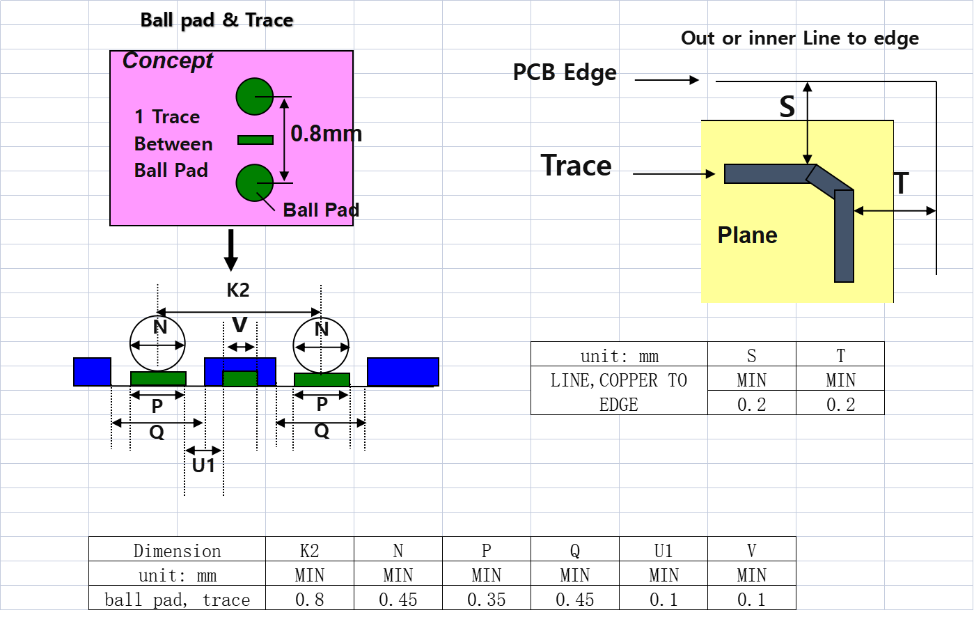
Minimum Trace Width and Spacing
BGA Minimum Size, Hole Position Tolerance, and Minimum Hole Diameter
- Minimum BGA size
- Common minimum BGA pitch is 0.2mm, essential for high-density component placement.
- Hole position tolerance
- Standard tolerance is ±0.05mm; high-precision manufacturing achieves ±0.025mm.
- Minimum hole diameter
- Mechanical drilling allows for 0.2mm holes, while laser microvias can go down to 0.1mm.
Impedance Control and High-Speed Signal Transmission
Minimum Solder Pad Opening
- Impact of solder pad opening size on reliability
- The smallest solder mask opening typically ranges from 0.05mm to 0.1mm, ensuring adequate soldering.
- If too small, soldering defects can occur; if too large, there’s a risk of short circuits.
Advanced PCB Features for High-Performance Applications
HDI (High-Density Interconnect) Technology
-
Differences between rigid, flex, and rigid-flex PCBs
- Rigid PCBs are used in most conventional electronics.
- Flex PCBs enable bendable, lightweight applications such as wearables.
- Rigid-flex PCBs combine both, ideal for complex three-dimensional designs.
-
Challenges of flexible PCBs
- Require higher precision manufacturing and durable bend-resistant materials.
- More expensive to produce compared to standard rigid PCBs.
Thermal Management: Aluminum PCBs and Heat Dissipation
Surface Finishes: ENIG, HASL, OSP, and More
- Pros and cons of different surface finishes
- ENIG (Electroless Nickel Immersion Gold): Ideal for high-reliability and long-life applications.
- HASL (Hot Air Solder Leveling): Cost-effective but has uneven surface issues.
- OSP (Organic Solderability Preservative): Eco-friendly, suited for short-term PCB storage.
Choosing the Right PCB Manufacturer
Quality Standards and Certifications
Production Lead Time and Prototyping Capabilities
- Importance of fast turnaround
- Accelerates product development and market launch.
- Supports small-batch prototyping for testing.
Customization and Manufacturing Flexibility
- How to determine if a manufacturer supports customization
- Ability to provide custom stack-ups, impedance matching, and plating processes.
- Capacity to meet material or design-specific requirements.
Final Checklist Before Ordering
- Confirm layer count, materials, copper thickness, and key process capabilities.
- Ensure the manufacturer holds necessary quality certifications.
- Verify lead times, prototyping services, and customization options.
Conclusion
Understanding PCB capabilities is essential for ensuring high-quality production. By evaluating factors such as materials, impedance, BGA size, and manufacturing precision, you can prevent costly errors and enhance product reliability. Selecting the right PCB manufacturer ensures your design translates into a functional, high-performance product.


 Quote
Quote