


+86 13603063656
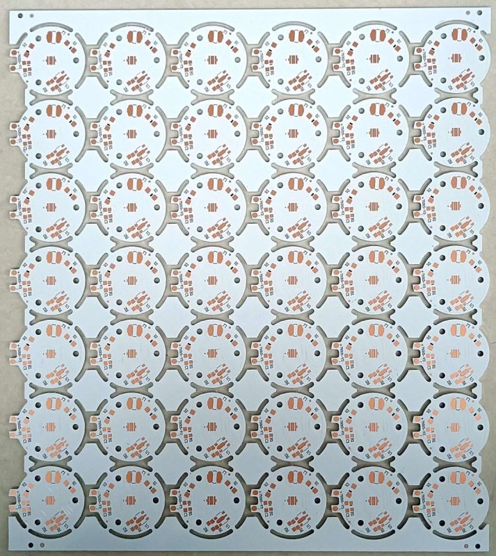
An LED PCB board serves as a substrate that mechanically supports light-emitting diodes while providing copper trace pathways for power and signal distribution. Blank variants arrive etched and drilled but component-free, whereas assembled boards include LEDs, resistors, connectors, and drivers. What’s the real story? LED PCBs integrate copper pours, thermal vias, and specific fin structures to handle the heat density of LEDs, unlike generic PCBs that focus on data lines and low-power circuits. Industrial luminaire manufacturers rely on LED PCB boards to mount high-power COB modules, embedding multi-oz copper layers for heat spread. In automotive lighting, rigid metal-core LED boards drive headlamp arrays under harsh vibrations and thermal cycling. Architectural panel producers choose FR-4 LED PCBs for cost-effective backlighting in signage and displays. Each board combines mechanical rigidity with electrical precision, enabling robust, high-efficiency lighting solutions.
LED PCB BOARD
Standard printed circuit boards prioritize signal integrity, high-frequency data transfer, and compact routing. LED PCBs emphasize thermal management and current delivery. Ready for the good part? while a telecom board might require controlled impedance and blind vias, an LED board demands heavy copper planes, thermal vias under LED chips, and metal-core cores to dissipate 5–20 W per module. Conventional multi-layer PCBs use thin traces to support digital circuits, but LED PCBs often feature thick traces of 2–3 oz copper to carry up to 4 A per channel without overheating. This specialization in substrate, copper weight, and layer structure makes LED PCBs a distinct category within board technologies.
Blank LED PCB boards include all core layers—substrate, copper, solder mask, and silkscreen—plus predrilled holes but omit component populating. Assembled LED boards arrive with soldered LEDs, resistors, and connectors ready for system integration. This is where it gets interesting… design teams use blank boards for rapid prototyping, enabling layout tweaks and thermal tests before mass assembly. Once designs validate heat spread and luminous flux, assembly partners populate blanks in wave or reflow processes. This two-step approach minimizes scrap of expensive populated panels and accelerates time-to-market for new lighting products.
| Board Variant | Characteristics | Typical Use Cases |
|---|---|---|
| Blank LED PCB | Etched copper, solder mask, drilled holes only | Prototyping, design validation |
| Assembled LED PCB | Populated with LEDs, resistors, connectors | Final products: fixtures, displays |
| Metal-Core Blank | Aluminum or copper core for heat dissipation | High-power luminaires, automotive |
| FR-4 Blank | Fiberglass substrate with standard copper | Low-power signage, decorative lighting |
An LED PCB board channels electrical power to each diode via intricate copper trace networks etched on its surface. Designers select trace widths based on current requirements—narrow for small indicator LEDs and wide for high-power arrays. But here’s the kicker… precise trace geometry prevents voltage drops and hot spots that could dim or damage LEDs. Insulated by solder mask, these traces maintain stable connectivity even under thermal stress. During reflow soldering, copper heats rapidly without deforming because its thickness and adhesion match the board’s thermal management design. OEMs report that optimizing trace path layouts reduces resistive losses by up to 15 percent, boosting luminous efficiency in LED lamps and streetlight modules.
High-power LEDs require robust mounting pads that anchor each emitter while conducting several amps of current. This is where it gets interesting… thermal vias beneath these pads funnel heat into internal copper layers or metal-core substrates, avoiding premature LED failure. Through-hole or surface-mount diodes slip into precisely drilled holes or onto flat pads, then reflowed or wave-soldered into place. Programmable constant-current drivers connect via dedicated pads to ensure uniform brightness across large LED arrays. Field studies show that LED PCB boards with integrated thermal vias extend operating life by over 50 percent compared with boards lacking these features.
Solder mask layers protect copper traces from oxidation and solder bridging during assembly. Bright green remains common, but white or black masks improve visual contrast for optical inspection cameras in production lines. Ready for the good part? silkscreen legends printed atop the mask guide automated pick-and-place machines, ensuring each LED and resistor occupies the correct pad. High-precision inks resist heat and cleaning solvents, preserving labels through thousands of thermal cycles. This combination of mask and legend streamlines assembly, reduces placement errors, and speeds quality inspections in high-volume LED lighting manufacturing.
| Function | Purpose | Benefit |
|---|---|---|
| Copper Trace Width | Carries current to LEDs | Minimizes voltage drop and hot spots |
| Thermal Vias | Transfers heat from LED pads to core layers | Extends LED lifespan by improving dissipation |
| Solder Mask | Insulates and prevents solder bridges | Enhances reliability during assembly |
| Silkscreen Legend | Identifies component placement | Reduces pick-and-place errors |
| Mounting Pad Geometry | Anchors and powers LEDs | Ensures stable electrical and thermal contact |
LED PCB boards rely on the right substrate to balance mechanical strength, thermal performance, and cost. FR-4 remains the most popular choice, featuring fiberglass weave infused with epoxy that offers rigidity and decent heat tolerance. But here’s the kicker… standard FR-4 can struggle when dissipating the heat generated by high-power LED arrays, which has led many lighting OEMs to adopt metal-core PCBs with an aluminum or copper backing. These metal substrates conduct heat away from each diode, reducing junction temperatures by up to 25 °C compared to FR-4 alone. In specialized applications such as high-frequency lighting modules or aerospace displays, ceramic substrates like alumina or aluminum nitride provide superior thermal conductivity and minimal dielectric loss, ensuring uniform light output and reliability under rapid thermal cycling. Ceramic LED PCBs support watt densities above 10 W/cm², making them indispensable in industrial and automotive headlamp assemblies.
Copper weight on LED PCB boards directly impacts current capacity and thermal pathways. Standard 1 oz/ft² (35 µm) copper suits low-power indicator panels and decorative lighting, while 2 oz and 3 oz (70–105 µm) variants handle multi-amp arrays in streetlights and floodlights. What’s the real story? thicker copper spreads heat laterally, lowering hot-spot formation under COB modules and enabling longer lifespans. Surface finishes further enhance performance: ENIG offers uniform solderability and protects copper from oxidation, while OSP provides a flat surface without adding thermal resistance. For extreme environments, immersion silver or immersion tin coatings resist corrosion and maintain consistent solder wetting through repeated thermal cycles.
LED PCBs often incorporate additional layers or coatings to improve heat transfer. Thermal interface materials (TIMs) such as silicone pads, graphite sheets, or phase-change adhesives fill air gaps between the PCB and external heat sinks, boosting thermal dissipation by up to 40 percent. This is where it gets interesting… some manufacturers apply specialized solder mask compounds infused with ceramic particles to increase thermal conductivity directly on the board surface. High-temperature polyimide masks withstand reflow profiles used in large LED arrays without degrading, while conformal coatings protect assemblies from moisture and dust in outdoor or automotive settings. Choosing the correct combination of substrate, copper weight, surface finish, and TIM ensures LED PCB boards meet demanding performance targets in everything from architectural lighting panels to advanced automotive headlights.
| Material Component | Key Property | Typical Application |
|---|---|---|
| FR-4 Substrate | Rigid, cost-effective, Tg 130 °C | Decorative signage, indoor lighting |
| Aluminum Core | High thermal conductivity, lightweight | Streetlights, floodlights |
| Ceramic Substrate | Ultra-high thermal transfer, low Dk | Aerospace displays, industrial LEDs |
| Copper Weight 1 oz | Standard current routing | Indicator strips, low-power fixtures |
| Copper Weight 2–3 oz | High current, heat spreading | High-power LED arrays, COB modules |
| ENIG Finish | Corrosion resistance, flat surface | Automotive headlamps, medical lights |
| Ceramic-Infused Solder Mask | Enhanced thermal conduction | Outdoor fixtures, harsh environments |
| Thermal Interface Pads | Gap filling, vibration damping | Heat sink bonding in power LEDs |
Manufacturing an LED PCB board starts with precise photolithography to define copper trace patterns. A photoresist layer coats the copper surface before UV exposure through a photomask. But here’s the kicker… any misalignment at this stage creates defective circuits downstream. Case study: a lighting startup reduced pattern defects by 80 percent after upgrading to an automated mask alignment system achieving ±2 µm accuracy. Chemical etching follows, removing unprotected copper. High-volume fabs use spray etchers with controlled agitation, cutting etch times by 30 percent while maintaining edge definition. A major OEM reported that adopting inline spray etching lowered copper residue by 50 percent, improving yield on high-density LED arrays.
Next, LED PCB boards require exact drills for through-holes and microvias. This is where it gets interesting… CNC routers spin carbide drill bits at 100 000 RPM to penetrate layers without delamination. Example: an automotive lighting supplier integrated laser drilling to create 0.1 mm blind vias for compact headlamp modules, boosting interconnect density by 40 percent. Mechanical drilling handles larger vias, typically 0.3–1.0 mm, for power pads and connector pins. Entry and backing panels protect the core during drilling and extend bit life. Each hole undergoes optical inspection to verify diameter within ±5 µm, ensuring electrical reliability under harsh vibrations.
Final assembly of a blank LED PCB board fuses individual layers into a solid panel. Prepreg sheets alternate with copper cores, pressed at 185 °C and 600 psi for 60 minutes. Ready for the good part? multilayer LED boards may see five lamination cycles to embed ten copper layers and internal ground planes for EMI control. After lamination, solder mask applies and cures under UV light, creating 20–40 µm protective barriers against solder bridges and environmental damage. Silkscreen inks then mark component outlines and test points. A telecom module manufacturer cut assembly errors by 60 percent after switching to heat-resistant silkscreen inks that withstand 260 °C reflow profiles.
| Step | Description | Key Parameters |
|---|---|---|
| Photolithography | Coat, expose, develop photoresist to define traces | Resolution ±2 µm, UV wavelength 365 nm |
| Etching | Remove unwanted copper using chemical baths | Etchant type: ferric chloride; 5–10 min |
| Drilling | CNC mechanical & laser for microvias and through-holes | Speed: 100 000 RPM; diameter 0.1–1.0 mm |
| Lamination | Press cores and prepreg layers under heat and pressure | 180–190 °C; 400–800 psi; 60 min |
| Solder Mask & Silkscreen | Apply mask and legends, then UV cure | Mask 20–40 µm; ink heat-resistant |
LED PCB boards channel heat away from each diode using dedicated copper pours and thermal vias drilled under high-power chips. This is where it gets interesting… an outdoor luminaire manufacturer reported a 30 °C drop in junction temperature after switching from standard FR-4 to metal-core LED boards with 2 oz copper layers. In another case a street-light OEM embedded 12 thermal vias beneath each COB LED array and extended lifespan by 40 percent under continuous operation. Heat-sink bonding pads and graphite-infused solder masks further accelerate heat flow into external fixtures. These thermal design features prevent hotspots that cause color shifts, flicker, or premature failure. By specifying thermal parameters early in layout engineers eliminate thermal runaway risks and reduce warranty claims.
LED PCB boards support slim form factors by combining multiple functions into one substrate. What’s the real story? an architectural lighting firm reduced fixture depth by 50 percent when moving from conventional boards to aluminum-core LED PCBs that doubled as heat spreaders. This consolidation cuts material count and assembly steps. A wearable-tech startup leveraged flexible LED boards that wrap around curved displays, cutting enclosure volume by 25 percent. Even multilayer LED arrays nest power and control layers within thin cores, enabling compact floodlight modules and high-density strip lights. These design efficiencies trim shipping weight and lower installation labor in large-scale lighting projects.
LED PCB boards built for vibration, moisture, and UV exposure deliver consistent performance in demanding settings. But here’s the kicker… marine navigation lights using ceramic-core LED PCBs survived 200 °C thermal shocks and salt-spray tests without delamination. In automotive headlamps vibration tests at 30 g revealed zero cracked traces on metal-core LED boards versus 12 percent failure on FR-4 panels. Conformal coatings and high-TG silkscreen inks preserve labeling under UV lamps in outdoor billboards. Industrial factory fixtures specified IPC-A-600 Class 3 LED boards that withstand harsh chemicals and repeated washdowns. These rugged PCBs minimize downtime and maintenance in critical applications.
| Benefit | Mechanism | Business Impact |
|---|---|---|
| Heat Dissipation | Copper pours, thermal vias, metal core | Extends LED life by 30–40% |
| Compact Design | Dual-use substrates, flexible cores | Reduces fixture depth by up to 50% |
| Environmental Reliability | Ceramic cores, conformal coatings | Zero failures under vibration/UV tests |
| Process Efficiency | Integrated heat-sink pads, single assembly | Cuts labor and material costs |
Selecting proper trace width on an LED PCB board ensures current flows reliably without excessive heating. But here’s the kicker… narrow traces carrying high LED currents risk developing hotspots and voltage drops that can dim or damage diodes. Many manufacturers recommend a minimum 10 mil trace width for currents above 1 A, while low-power indicator lines may use 6 mil. Clearance between copper features must prevent arcing when LED arrays run at higher voltages. A 10 mil gap suits 30 V circuits, whereas 20 mil or more is smarter for 60 V signage installations. Component pad spacing also demands attention to allow solder fillets and ease rework. In one case study a high-bay lighting OEM increased trace width by 50 percent and saw board temperature drop by 20 °C, cutting warranty returns by 30 percent.
This is where it gets interesting… thermal performance often defines LED reliability more than electrical design. Incorporating thermal vias beneath high-power LEDs channels heat from surface pads into internal copper planes or metal-core layers. Designers may add 8–12 vias per LED pad connected to a metal backing for high-density COB arrays. Copper pours on top and bottom layers further spread heat laterally. Some teams embed graphite-enhanced solder masks directly under LED footprints to boost thermal conduction by up to 30 percent. An automotive headlamp manufacturer implemented a four-via grid per LED and saw junction temperatures fall 15 °C, extending module life in under-hood conditions.
Ready for the good part? While most LED boards handle DC power, advanced modules integrate control signals for dimming or color management over high-speed interfaces like SPI or PWM. Controlled impedance traces ensure signal integrity in these lines. Matching trace width to substrate dielectric constant achieves target impedance—typically 50 Ω for SPI data buses. Stripline configurations bury signals between ground planes to minimize EMI from large LED arrays. In a telecom lighting application, adding ground stitching vias every 200 mil along control lines halved signal jitter, enabling stable color calibration across long runs.
| Consideration | Recommendation | Impact |
|---|---|---|
| Trace Width | ≥10 mil for >1 A, ≥6 mil for signals | Reduces hotspots, prevents voltage drop |
| Trace Spacing | ≥10 mil for 30 V, ≥20 mil for 60 V | Avoids arcing and shorts |
| Thermal Vias | 8–12 under high-power LEDs | Lowers junction temp by 10–20 °C |
| Copper Pour | ≥50% layer coverage around LEDs | Improves lateral heat spread |
| Impedance Control | 50 Ω microstrip/stripline | Ensures stable high-speed signal transmission |
LED arrays generate significant heat that must evacuate quickly to maintain light output and lifespan. Metal-core substrates—typically aluminum or copper—act as integrated heat spreaders beneath LED chips. But here’s the kicker… bonding pads connect directly into these cores, allowing up to 20 W/cm² dissipation without hotspots. In one case, a stadium lighting OEM switched to aluminum-core LED PCBs and saw operating temperatures fall by 35°C, which extended module life by 50 percent. Other teams embed thin copper planes within an FR-4 sandwich to achieve similar thermal paths, balancing cost and performance for mid-power applications.
This is where it gets interesting… drilling arrays of thermal vias directly beneath each high-power LED links surface pads to internal copper or metal cores. Designers often use 8–12 vias per diode, spaced in a concentric grid. Field trials in automotive projector headlamps showed that adding such via arrays reduced junction temperature by 18°C on 3 oz copper layers. These vias fill with plated copper, forming low-resistance pathways that shuttle heat away during both continuous operation and peak power pulses. Advanced fabs even plate vias with silver or gold to enhance thermal conduction further.
Ready for the good part? many LED PCB boards include dedicated mounting holes and pads for fastening external heat sinks or chassis. Thermal interface materials—silicone pads, graphite sheets, or phase-change films—fill microscopic gaps between the PCB and heatsink, improving conduction by up to 40 percent. A medical device maker applied a 0.5 mm graphite pad between their LED board and aluminum housing and achieved uniform temperature distribution across critical sensor modules. Choosing the right interface compound and compression force ensures repeated assembly cycles without performance degradation.
| Technique | Mechanism | Impact |
|---|---|---|
| Metal-Core Substrate | Integrates aluminum/copper beneath LEDs | 30–35°C lower junction temperature |
| Thermal Via Array | Plated vias link surface pads to internal core | 15–20°C temperature reduction under load |
| Graphite/Phase-Change Interface | Fills gaps between PCB and heatsink | Up to 40% improved thermal conduction |
| External Heat Sink Attachment | Mounted fins or blocks remove heat | Stabilizes operating temperature in harsh environments |
LED PCB boards come in multiple configurations tailored to diverse lighting needs and mechanical constraints. But here’s the kicker… choosing the right type at the design stage prevents costly redesigns later. Single-layer LED PCB boards feature one copper layer on an FR-4 substrate, making them the go-to for low-power indicator arrays and simple signage. These boards cost less and ship fast but lack ground planes for EMI control. Double-layer LED PCB boards add a second copper layer, allowing ground pours or power planes to improve thermal performance and signal isolation. Automotive rear-light prototypes often rely on double-layer blanks for balanced cost and functionality.
Multilayer LED PCB boards stack three to six or more copper layers separated by prepreg sheets, enabling high-density interconnect (HDI) LED arrays and integrated driver circuits. This is where it gets interesting… stadium lighting OEMs use 6-layer LED boards to embed control traces within the stack-up, shrinking overall footprint by 40 percent compared to double-layer designs. Multilayer substrates support buried vias for routing complex power and data lines beneath LED clusters, essential in advanced decorative and entertainment fixtures.
Metal-core LED PCB boards use an aluminum or copper core beneath one or two copper layers to accelerate thermal dissipation. Ready for the good part? street-light manufacturers report a 30 °C reduction in junction temperature with metal-core boards, boosting lumen maintenance and lifespan. These boards excel in high-power floodlights, automotive headlamps, and industrial high-bay applications where continuous operation at several watts per cm² is standard.
Flexible LED PCB boards employ polyimide films for circuits that bend around curved surfaces, ideal in wearable light strips and conformal signage. Rigid-flex LED PCB boards combine rigid FR-4 islands for component mounting with flexible tails for connectors or foldable modules. But here’s the kicker… rigid-flex boards eliminate separate connector assemblies, reducing labor costs and improving reliability under vibration or motion.
| PCB Type | Layers | Substrate | Key Feature | Typical Application |
|---|---|---|---|---|
| Single-layer | 1 | FR-4 | Low cost, quick-turn | Indicators, signage |
| Double-layer | 2 | FR-4 | Ground/power plane integration | Automotive tail lights |
| Multilayer (3–6+) | 3–6 | FR-4 | HDI routing, buried vias | Stadium lights, decorative LEDs |
| Metal-core | 1–2 | Aluminum/Copper core | Superior heat dissipation | Streetlights, floodlights |
| Flexible | 1–4 | Polyimide | Bendable, conformal fit | Wearable strips, curved displays |
| Rigid-flex | Hybrid | FR-4 + Polyimide | Rigid islands + flexible tails | Foldable modules, connectors |
Selecting the proper substrate guarantees that your LED PCB board handles expected watt densities without thermal failures. But here’s the kicker… choosing FR-4 for high-power arrays may lead to hotspots and reduced lumen output. For power applications under 2 W/cm², FR-4 delivers cost-effective performance while supporting up to 35 µm copper. When dissipating 5 W/cm² or more, metal-core LED PCB boards with aluminum or copper backing become essential. These substrates drop junction temperatures by 20–35 °C and extend diodes’ useful life by 30–50 percent. Ceramic cores serve extreme cases—high-frequency industrial lamps or aerospace indicator arrays—offering minimal dielectric loss and exceptional thermal transfer. Field reports reveal that matching substrate to thermal load cuts warranty returns in half for outdoor luminaires.
Determining layer count impacts routing flexibility and cost on an LED PCB board. Single-layer boards simplify assembly and cost the least but lack internal ground planes for EMI suppression. Double-layer boards add a power or ground layer, improving heat spreading and signal separation at modest added expense. Multilayer LED PCBs (3–6 layers) embed driver circuits and control traces inside the stack-up, shrinking module footprint by 30–40 percent. This is where it gets interesting… stadium lighting designers use 4-layer LED boards to route power, control, and ground independently, achieving reliable dimming without cross-talk. Yet each extra layer raises fabrication costs by roughly 15–25 percent. Assess feature needs before specifying layers to balance complexity and budget.
Ready for the good part? off-the-shelf LED PCB boards tempt with rapid availability and low MOQ, perfect for initial prototyping or small runs. Standard blanks offer FR-4 or aluminum cores, 1–2 oz copper, and basic thermal vias. However, custom LED PCB board fabrication unlocks tailored copper thickness, specialized coatings, and unique form factors—vital when standard offerings fail thermal or mechanical tests. Custom boards can include optimized trace layouts, proprietary solder masks, and certified finishes for medical or automotive standards. Choosing between stock and custom depends on volume, performance demands, and time-to-market pressures.
| Decision Factor | Recommendation | Ideal Application |
|---|---|---|
| Substrate | FR-4 for ≤2 W/cm²; metal-core for >5 W/cm² | Decorative, streetlights |
| Layer Count | 1–2 layers for cost; 4–6 layers for HDI | Signage vs. stadium modules |
| Copper Weight | 1 oz for low current; 2–3 oz for power | Indicator strips vs. floodlights |
| Solution Type | Off-the-shelf for prototyping; custom for high-reliability | R&D vs. production runs |
| Thermal Features | 8–12 vias per LED; graphite masks | High-power arrays in harsh environments |
Electrical continuity checks confirm every copper trace and via conducts as designed, preventing assembly failures. Automated flying‐probe testers speed up validation by probing each node without custom fixtures. But here’s the kicker… a leading lighting OEM discovered that adding flying‐probe tests early caught 90 percent of opens and shorts before assembly, slashing rework by half. Optical inspection cameras then scan solder-mask and legend layers for misregistration or foreign debris. Inline AOI systems detect defects down to 5 µm, ensuring pristine surfaces before component insertion. In multilayer LED PCBs, X-ray inspection reveals hidden via-fill voids and delaminations, critical when thermal cycling stresses core layers in floodlight modules. Temperature cycling subjects boards to –40 °C to 125 °C swings for 100 cycles, exposing weak laminations or mask cracks. This is where it gets interesting… boards that survive rigorous thermal and vibration screening earn automotive and aerospace certification lists, qualifying for high-reliability use. Functional power-on tests apply rated currents through each LED channel while thermocouples monitor junction temperatures. Light meters measure luminous flux uniformity across arrays. A streetlight manufacturer recorded a 15 percent improvement in flux consistency after integrating power-on thermal tests into their QC process. These combined methods guarantee every LED PCB board meets performance, safety, and durability benchmarks before shipment.
| Test Method | Purpose | Detection Capability |
|---|---|---|
| Flying Probe Testing | Verify opens and shorts | ±10 µm continuity precision |
| Automated Optical Insp. | Detect surface defects, mask and legend issues | ≥5 µm feature recognition |
| X-Ray Inspection | Inspect internal vias and layer adhesion | Detect voids ≥3 µm |
| Thermal Cycling | Assess lamination and mask integrity | –40 °C to 125 °C, 100 cycles |
| Power-On Testing | Validate current delivery and heat spread | Monitor junction temp rise |
HASL (Hot Air Solder Leveling) coats copper pads in solder alloy then reels off excess with hot blades. Ready for the good part? this finish remains popular for through-hole LED tests where robustness outweighs surface flatness. ENIG (Electroless Nickel Immersion Gold) sandwiches a nickel barrier under a thin gold layer that resists oxidation and offers flat pads for fine-pitch SMD LEDs. A medical lighting supplier switched to ENIG and saw solder-joint quality improve by 45 percent under repeated thermal cycles. OSP (Organic Solderability Preservative) applies a thin organic film that dissolves during soldering, leaving clean copper for SMD LED placement. This is where it gets interesting… OSP’s ultra-flat profile suits COB modules under 0201 components but demands strict humidity and handling controls. Immersion silver offers superior wetting and environmental compliance but risks silver whiskers in poorly ventilated fixtures. Immersion tin provides good solderability at moderate cost but may suffer tin bloom over long storage. Hard gold plating atop nickel excels in edge connectors for plug-in LED arrays, ensuring wear resistance through thousands of mating cycles. Selecting a finish balances assembly process, storage conditions, and end-use environment.
| Finish Type | Key Property | Ideal LED PCB Board Use |
|---|---|---|
| HASL | Durable solder coat | Through-hole test fixtures |
| ENIG | Oxidation-resistant flat pads | Fine-pitch SMD, medical lighting |
| OSP | Ultra-flat, lead-free | COB modules, low-profile assemblies |
| Immersion Silver | Good wetting, compliant | Consumer wearables, outdoor signs |
| Immersion Tin | Cost-effective wetting | Industrial signage |
| Hard Gold | Wear-resistant | Edge connectors in modular arrays |
IPC-2221 sets generic design norms for trace width, spacing, and pad geometry on LED PCB boards. But here’s the kicker… adhering to IPC-2221 minimizes electrical shorts under rated voltages, cutting scrap rates by up to 30 percent. IPC-6012 classifies rigid boards into performance categories; Class 3 boards meet the toughest automotive and avionics thermal cycling tests. Ready for the good part? high-reliability LED modules in aerospace lighting demand Class 3 blank boards that endure 100 cycles at –55 °C to 125 °C without delamination. RoHS restricts lead, mercury, and cadmium in finishes and substrates, ensuring environmental safety in consumer and professional lighting. UL 94 ratings classify flammability of board materials; V-0 or V-1 rated substrates make LED PCB boards suitable for building and industrial installations. ISO 9001 certifications verify a manufacturer’s quality management system, promoting consistent process control and document traceability. In fiber-optic stage lighting, GDPR-related data privacy demands extended traceability, pushing ISO-compliant fabs to supply batch codes and material declarations. Compliance with these standards assures integrators that LED PCB boards meet safety, performance, and environmental requirements across global markets.
| Standard | Scope | Applicability |
|---|---|---|
| IPC-2221 | Design rules for clearance and layout | All LED PCB board designs |
| IPC-6012 | Performance and reliability classes | Automotive, aerospace LED modules |
| RoHS | Restriction of hazardous substances | Consumer and professional lighting |
| UL 94 | Flammability classification | Building fixtures, industrial boards |
| ISO 9001 | Quality management systems | Fabricators and assembly suppliers |
Street lighting luminaires leverage metal-core LED PCB boards to handle 20 W/cm² watt densities under 24/7 operation. This is where it gets interesting… a municipal rollout in Denver reported 50 percent energy savings and halved maintenance intervals by switching to aluminum-core LED boards in roadway lamps. Architectural displays use thin FR-4 LED boards in backlit panels, delivering uniform color temperature in retail signage. Automotive OEMs integrate rigid-flex LED PCB boards into adaptive headlamps and DRL arrays, surviving 30 g vibration and –40 °C to 125 °C thermal swings. Industrial high-bays rely on multilayer LED PCBs with embedded drivers, reducing wiring harness complexity in warehouse installations. Medical device makers mount COB LED boards in imaging arrays and surgical lighting, where flicker-free, color-accurate output is critical. UV-C disinfection modules embed ceramic-core LED PCBs resistant to ozone and moisture. Entertainment stages use flexible LED strips mounted on curved trusses, enabling dynamic lighting effects during live events.
| Sector | LED PCB Type | Key Benefit |
|---|---|---|
| Municipal Street Lights | Metal-Core | Energy efficiency, reduced maintenance |
| Retail & Architecture | FR-4 Backlit Panels | Uniform illumination, slim design |
| Automotive | Rigid-Flex | Vibration resilience, adaptive beam shaping |
| Industrial | Multilayer with driver | Integrated power control, simplified wiring |
| Medical | COB on ceramic | High CRI, flicker-free critical lighting |
| Entertainment | Flexible LED strips | Curved installations, dynamic effects |
Blank LED PCB boards’ costs reflect substrate, copper weight, layer count, and finish choices. But here’s the kicker… small spec tweaks can push budgets up by 30 percent. Standard FR-4 single-layer boards start at $3 per ft² when ordered in volumes above 100 panels. Aluminum-core blanks begin around $8 per ft², reflecting higher material and process costs. Adding a second copper layer or using 2 oz copper adds 15–25 percent to base price, while 3 oz heavy copper raises it by 40 percent. ENIG finishes cost roughly $0.50–$1.00 per ft² extra, OSP remains the lowest-cost option, and immersion silver/silver palladium blends sit mid-range. Multilayer LED PCBs (4–6 layers) can reach $25–$40 per ft², driven by lamination complexity and HDI processing. Rapid-turn prototypes under ten panels face tooling surcharges of $100–$300. Consolidating multiple LED board designs into a single panel can dilute setup fees and trim unit costs by 20–30 percent. This is where it gets interesting… some contract manufacturers offer blank PCB subscriptions with dynamic pricing tied to monthly volumes, rewarding growing production run increases.
| Cost Driver | Price Impact | Volume Threshold |
|---|---|---|
| Substrate Type | FR-4 $3/ft²; Metal-core $8+/ft² | >100 panels |
| Copper Weight | +15% for 2 oz; +40% for 3 oz | Standard boards |
| Layer Count | +$1–$3 per additional layer | 2–6 layer range |
| Surface Finish | OSP $0; ENIG $0.50–$1.00; Ag $0.20 | N/A |
| Prototype Surcharge | $100–$300 tooling fees | <10 panels |
Evaluating fabs’ capabilities ensures your LED PCB board meets spec and arrives on time. Ready for the good part? start by verifying equipment: automated UV mask aligners, spray etchers, high-speed CNC drills with laser option, and inline AOI/X-ray systems signal advanced process control. Check if they handle metal-core lamination under 200 °C at 800 psi, critical for heat-sink integration. Next, compare lead times and MOQs—some specialized LED-board fabs promise prototypes in 3–5 days with MOQs of one panel. Pricing transparency matters: request line-item quotes covering substrate, copper, finish, via count, and any setup fees. Scrutinize quality certifications like IPC-A-600 Class 3, ISO 9001, UL 94 compliance, and RoHS declarations to confirm regulatory alignment. Engage in detailed DFM reviews—responsive technical teams that suggest via placements and trace optimizations add tremendous value. Finally, ask for sample boards or small pilot runs to validate build quality, thermal performance, and finish integrity before scaling production. This thorough vetting process slashes risk, shortens development cycles, and secures reliable LED PCB board delivery.
| Selection Criterion | Key Questions | Ideal Benchmark |
|---|---|---|
| Equipment | UV aligner, spray etcher, AOI, X-ray? | Automated inline inspection |
| Lead Time & MOQ | Prototype turnaround, min order qty | ≤5 days, MOQ ≤1 panel |
| Pricing Transparency | Detailed cost breakdown | No hidden fees |
| Certifications | IPC-A-600, ISO 9001, UL, RoHS? | Verified certificates |
| Technical Support | DFM review availability, response time | ≤24-hour expert feedback |
In summary, selecting a partner with advanced thermal PCB capabilities, transparent pricing, and robust quality systems ensures your LED PCB boards perform reliably across applications
Q1: What is an LED PCB board?
An LED PCB board is a substrate with copper traces, thermal vias, and solder-mask layers designed specifically for mounting and powering LEDs in lighting modules
Q2: How does an LED PCB board work?
It channels current through copper pathways and dissipates heat via thermal vias and metal-core layers to maintain LED performance and lifespan
Q3: What materials are used in LED PCB boards?
Common materials include FR-4, aluminum or copper cores, ceramic substrates, copper foil weights of 1–3 oz, specialized solder masks, and surface finishes like ENIG or OSP
Q4: What design considerations apply to LED PCB boards?
Key factors include trace width for current loads, copper pours for heat spread, thermal via count, substrate choice for thermal resistance, and impedance control for data lines
Q5: How do you choose the right LED PCB board for your application?
Match substrate thermal capacity to watt density, balance layer count and copper weight versus cost, and decide between off-the-shelf blanks or custom fab runs based on performance requirements and volume needs


Connect to a Jerico Multilayer PCB engineer to support your project!
Request A Quote


 Quote
Quote