


+86 13603063656
You struggle with selecting the right PCB foundation for your assembly line and managing yield concerns. But here’s the kicker… a bare PCB board offers a clean slate—etched copper on substrate ready for your components—so you avoid hidden defects and streamline first-pass success. You’ll see how these boards define your product’s reliability, control costs through design-for-manufacture best practices, and integrate with automated assembly lines. Backed by IPC and UL expertise, this guide equips you to choose, design, and qualify bare boards that meet rigorous B2B demands.
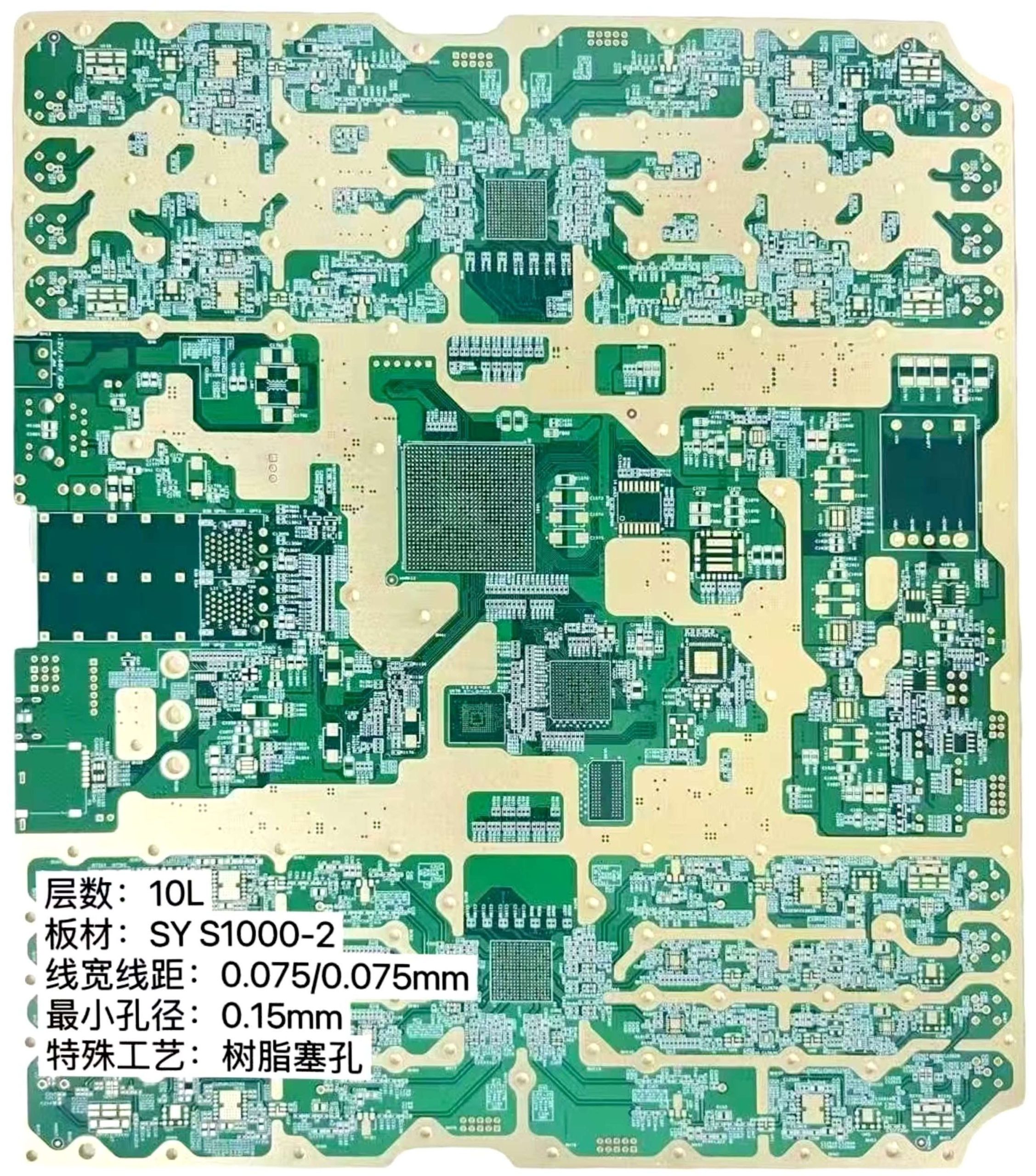
Bare PCB Board
Bare PCB boards arrive without components, featuring only substrate layers, copper traces, solder mask, and silkscreen. This is where it gets interesting… substrates like FR-4 give mechanical support while copper foil defines signal routing. A solder mask coating prevents shorts during soldering, and silkscreen inks add assembly labels. Unlike fully assembled boards, bare boards let you control parts placement, soldering profiles, and testing workflows in-house or at contract manufacturers. Key parameters include copper weight (1–4 oz), layer count (1–20+), and finish type (HASL, OSP, ENIG). Bare boards serve as the critical interface between design and assembly.
| Attribute | Description | Typical Range |
|---|---|---|
| Substrate | Fiberglass epoxy (FR-4) or polyimide | Tg 130 °C (FR-4), 260 °C (Polyimide) |
| Copper Thickness | Copper foil weight per square foot | 1 oz–4 oz |
| Layers | Number of conductive layers | 1–20+ |
| Solder Mask | Protective polymer over copper | 20–40 µm |
| Silkscreen | Assembly legend and logos | 0.1–0.15 mm stroke width |
Manufacture begins by laminating copper foil to substrate, then coating with photoresist. Ready for the good part? UV exposure imprints your Gerber-defined pattern onto the resist. Developing removes unexposed areas and chemical etching strips away unwanted copper. Next, CNC drills create holes and vias with ±0.05 mm accuracy. Laser drilling handles microvias for HDI boards. Electroplating deposits copper inside via barrels (10–25 µm), ensuring conductivity through all layers. Multilayer boards then undergo prepreg lamination under 10 bar at 180 °C. After lamination, final imaging, etching, and drilling refine features. Automated optical inspection compares each board against golden files, flagging open circuits or shorts. X-ray systems check buried vias. Flying-probe or bed-of-nails tests verify continuity and isolation across thousands of nets. This sequence, governed by IPC-6012 standards, produces bare boards that meet your performance requirements.
| Step | Key Detail | Tolerance/Standard |
|---|---|---|
| Photoresist Imaging | UV exposure of dry-film resist | ±0.05 mm resolution |
| Copper Etching | Chemical removal of unwanted copper | ±0.1 mm trace width |
| Drilling | CNC/laser holes and vias | ±0.05 mm hole position |
| Via Plating | Electroplating barrel thickness | 10–25 µm copper |
| Lamination | Bonding layers under heat and pressure | 0.1 mm layer registration |
| AOI | Automated optical inspection | IPC-6012 Class 2 |
| Electrical Testing | Flying-probe or bed-of-nails | 100% net coverage |
Materials determine a board’s electrical performance and environmental resilience. But here’s the kicker… selecting the right substrate sets the stage for thermal stability, signal integrity, and mechanical strength under stress Cyclops. FR-4 remains the workhorse: a fiberglass-woven epoxy laminate offering Tg around 130 °C, moderate dielectric constant, and cost-effectiveness. It handles most control-logic and general-purpose PCBs without breaking a sweat. Polyimide substrates push Tg above 260 °C and deliver flexible characteristics for bendable or rigid-flex boards used in automotive sensors and wearable electronics. What’s the real story? polyimide’s higher coefficient of thermal expansion requires careful design to avoid layer separation during thermal cycling.
Ceramic substrates such as alumina or aluminum nitride boast exceptional thermal conductivity—20–170 W/m·K—ideal for high-power LED assemblies or RF power amplifiers. Their low dielectric loss and minimal moisture absorption support GHz-range applications without signal attenuation. This is where it gets interesting… metal-core PCBs use aluminum or copper as the base, combining a dielectric layer and copper traces atop a metal heat-spread layer. These MCPCBs manage heat in LED arrays or power converters, maintaining junction temperatures and boosting reliability.
Copper foil choices range from 1 oz (35 µm) to 4 oz (140 µm) per square foot. Heavy copper options enable currents up to 30 A per trace without significant voltage drop. Prepreg films—epoxy-impregnated glass cloth—bond layers in multilayer boards, controlling dielectric thickness (usually 0.15–0.4 mm) for impedance consistency. Surface finishes also count: HASL guards copper but leaves slight topography; OSP applies an organic film for flat lead-free assembly; ENIG deposits nickel and gold layers for fine-pitch SMT and excellent shelf life. Each finish interacts differently with solder and flux chemistries.
By matching substrate Tg, copper weight, dielectric constant, and finish characteristics to your end-use environment—be it consumer gadget, automotive ECU, or aerospace avionics—you ensure bare PCBs withstand thermal stresses, maintain signal fidelity, and deliver long-term field reliability without surprise failures.
| Material | Key Property | Typical Use Case |
|---|---|---|
| FR-4 | Tg 130 °C, moderate CTE | General-purpose PCBs |
| Polyimide | Tg 260 °C, flexible, high CTE | Flex/rigid-flex, high-temp electronics |
| Ceramic | Thermal conductivity 20–170 W/m·K | High-power LEDs, RF power modules |
| Metal Core (Al/Cu) | Heat spread, mechanical rigidity | LED lighting, power converters |
| Copper Foil | Conductivity 58 MS/m, weights 1–4 oz | Trace current capacity |
| Prepreg | Dielectric bonding layer, 0.15–0.4 mm | Multilayer lamination |
| HASL | 3–5 µm solder coating | Through-hole, general SMT |
| OSP | 0.2–0.5 µm organic film | Lead-free, flat surface |
| ENIG | 3–6 µm Ni, 0.05–0.1 µm Au | Fine-pitch SMT, long shelf life |
Effective design strikes a balance between performance and manufacturability. Ready for the good part? Trace width and spacing must align with copper weight and current requirements. Narrow traces on heavy copper boards risk overheating under load if their width doesn’t scale accordingly. Use IPC-2152 or fabricator guidelines to calculate minimum trace widths that handle your peak currents without excessive temperature rise. Layer stack-up planning follows: a balanced arrangement of signal and plane layers prevents warpage and controls impedance. What’s the real story? grouping all high-speed nets on a single layer without adjacent reference planes yields EMI and reflection issues.
Via strategy drives routing density and thermal management. Microvias suit high-density interconnects in HDI boards, while through-holes serve power planes and mechanical support. Blind and buried vias reduce board area but increase process complexity and cost. Thermal relief pads around drilled holes help spread heat away from power components and simplify soldering, preventing tombstoning. This is where it gets interesting… thermal via arrays under power devices connect outer copper layers to internal heat-spreader planes, whisking away heat in high-power applications.
Solder mask clearance must respect fine-pitch component pads. Maintaining mask dam widths above 0.1 mm prevents mask lifting during reflow, which could cause shorts. Silkscreen legends, offering assembly guidance, should avoid overlapping pads or vias, or they risk misalignment and ink bleed. Component placement areas need ample keep-out zones for stencil printing and pick-and-place accuracy.
Impedance control for RF and high-speed digital signals demands strict dielectric thickness tolerances (±10 percent). Confirm material datasheets detail dielectric constant stability over temperature. Layer-to-layer registration tolerances—often ±0.1 mm—ensure signal integrity and proper via alignment. Design rule checks against IPC-2221 or IPC-6012 Class 2 prevent layout violations that later cause fabrication rejects. By focusing on trace geometry, stack-up balance, via configuration, mask integrity, and impedance consistency, your bare PCB design translates into reliable, manufacturable boards that meet performance targets and assembly yield goals.
| Parameter | Recommendation | Impact on Yield |
|---|---|---|
| Trace Width | ≥ 3 × copper weight in oz | Handles current, reduces hot spots |
| Trace Spacing | ≥ 2 × minimum line width | Prevents shorts and assembly defects |
| Layer Stack-Up | Balanced signal/plane layer distribution | Minimizes warpage, maintains impedance |
| Via Types | Microvias for HDI, through-holes for power | Optimizes routing, thermal conduction |
| Thermal Vias | Arrays under power components | Enhances heat dissipation |
| Solder Mask Web Width | ≥ 0.1 mm between pads | Avoids mask peeling and solder bridging |
| Silkscreen Placement | Clear of pads/vias | Prevents ink bleed and misalignment |
| Impedance Tolerance | ±10% dielectric thickness | Maintains signal integrity |
| DRC Standard | IPC-2221 or IPC-6012 Class 2 | Ensures manufacturability and quality |
But here’s the kicker… catching defects before assembly saves time and cost
Visual inspection kicks off every bare board run under bright LED lighting with trained operators scanning for surface contamination, copper whiskers, or irregular masking. This manual step catches obvious flaws early—like stray resin beads on pads or scratches across traces—that automated systems might miss. What’s the real story? Automated Optical Inspection (AOI) follows, using high-resolution cameras to compare each board against its golden Gerber mask. AOI flags issues such as missing pads, under-etched traces, or solder-mask misregistration with over 99 percent accuracy. Ready for the good part? X-ray inspection then reveals hidden inner-layer faults and via-fill voids that AOI cannot detect. By examining plated through-holes and buried microvias, X-ray systems ensure copper plating meets thickness and adhesion specs.
Next comes electrical testing. Flying-probe testers deploy programmable spring-loaded needles to make contact with pad locations defined in test files. Each probe applies a small voltage to verify continuity across intended nets and isolation between separate circuits. For high-volume runs, bed-of-nails fixtures contact hundreds of points simultaneously, completing net checks in seconds rather than minutes. Loose or missing connections lead to immediate fail codes and board rejection before downstream work. What’s the real story? Some fabricators add environmental stress tests like thermal cycling or humidity chamber exposure on sample boards, verifying material and plating resilience under accelerated aging conditions. This step validates that solder masks and dielectric layers will endure field conditions without cracking or delamination.
By layering visual, AOI, X-ray, and electrical methods—and supplementing with stress tests—fabricators ensure each bare PCB board meets IPC-6012 class-level criteria for reliability. This multi-modal inspection workflow keeps yields high, cuts rework, and guarantees your assembly line receives ready-to-populate boards built to exact specifications.
| Inspection Stage | Method | Purpose |
|---|---|---|
| Visual Check | Manual under bright lights | Spot surface defects and contamination early |
| AOI | High-resolution cameras | Verify trace integrity and mask alignment |
| X-ray Inspection | X-ray imaging | Detect inner-layer misregistration and via voids |
| Flying-Probe Test | Programmable needles | Check continuity and isolation for prototypes |
| Bed-of-Nails Test | Fixed-pin fixtures | Rapid full-net validation in volume production |
But here’s the kicker… industry standards define every bare PCB’s quality benchmarks
IPC-6012 sits at the core, specifying performance requirements for rigid PCBs. It outlines copper thickness tolerances, dielectric breakdown voltages, and hole-wall plating integrity. Boards built to IPC-6012 class 2 suit general electronics, while class 3 covers critical applications like aerospace or medical devices. What’s the real story? Complementing this, IPC-2221 details design rules—minimum trace widths, spacing, and insulation resistance values—ensuring your layout conforms before fabrication begins. Ready for the good part? UL 94 categorizes substrate flammability from V-0 down to V-2, dictating how quickly materials self-extinguish when exposed to flame, critical for safety-certified equipment.
Environmental regulations round out compliance. RoHS restricts hazardous substances such as lead and mercury to trace ppm levels, forcing fabricators to source compliant materials and provide declarations of conformity. Meanwhile, REACH regulates chemicals in Europe, requiring registries of any substances of very high concern (SVHC) in your dielectric, copper foil, or mask formulations. What’s the real story? IEC 61189 prescribes test methods for PCB materials—mechanical, electrical, and environmental—covering humidity, thermal shock, and dielectric rigidity. Zirconia or alumina ceramic laminates for RF boards must pass these tests to ensure minimal signal loss across GHz frequencies.
By aligning design and production to IPC-6012, IPC-2221, UL 94, RoHS/REACH, and IEC test methods, fabricators deliver bare PCB boards that meet stringent global requirements. This compliance framework reduces field failures, secures regulatory approvals, and gives you the confidence that every board meets the quality standards your applications demand.
| Standard | Scope | Key Requirements |
|---|---|---|
| IPC-6012 | PCB performance qualification | Copper thickness, plating integrity, dielectric tests |
| IPC-2221 | Generic design rules | Trace/spacing, insulation resistance, thermal parameters |
| UL 94 | Material flammability | V-0 to V-2 ratings |
| RoHS/REACH | Hazardous substance limits | Lead, mercury, cadmium thresholds |
| IEC 61189 | Test methods for PCB materials | Humidity, thermal shock, dielectric breakdown |
Multilayer bare PCB boards stack alternating cores and prepreg films to achieve high-density routing and performance. But here’s the kicker… each internal copper layer forms its own signal or plane network, enabling compact designs where single- or double-sided boards simply fall short. In multilayer boards you’ll see dedicated power and ground planes sandwiched between signal layers, reducing electromagnetic interference and providing stable reference planes for high-speed traces. What’s the real story? Designers allocate layers strategically: inner planes carry power distribution and shielding, outer layers host component routing, and buried or blind vias connect selected layers without consuming precious real estate on outer surfaces.
Lamination accuracy becomes mission-critical. Prepreg bonding under pressures above 10 bar and temperatures near 180 °C ensures void-free adhesion; misregistration greater than ±0.05 mm between layers can lead to trace misalignment and electrical shorts after drilling. After lamination, all-layer drilling uses precision CNC or laser drills to create through-holes, blind microvias, and buried vias. Microvias under 100 µm diameter increase routing density but require specialized laser equipment and controlled aspect ratios to avoid voids or copper “necking.” Ready for the good part? Advanced fabricators perform inner-layer AOI before lamination and X-ray verification after, catching alignment or fill defects early and saving costly rework on completed panels.
Thermal management also changes. Heat generated by components on outer layers must traverse multiple substrates to reach internal planes. Designers embed thermal via arrays—densely packed via chains under power elements—connecting outer copper to inner copper heat-spreaders. Thermal simulations identify hotspots before fabrication, guiding via placement for optimal heat flow. This reduces board warpage and extends assembly lifespan.
By layering signal and plane copper, controlling via types, and optimizing lamination and inspection, multilayer bare PCBs deliver unmatched flexibility for complex B2B products such as telecom backplanes, medical imaging systems, and aerospace control units. The result: boards that pack more functionality into less space without compromising signal integrity or reliability.
| Feature | Single/Double-Sided | Multilayer |
|---|---|---|
| Layer Count | 1–2 copper layers | 4–20+ copper layers |
| Routing Density | Limited outer-layer only | High-density internal & external routing |
| EMI Control | Basic shielding | Dedicated ground/power planes |
| Via Options | Through-holes only | Through, blind, buried, microvias |
| Lamination Pressure | Not required | ≥10 bar at 180 °C |
| Inspection Methods | AOI, electrical tests | Inner-layer AOI, X-ray, electrical tests |
Protective surface finishes guard copper from oxidation and ensure reliable soldering during assembly. What’s the real story? Hot Air Solder Leveling (HASL) remains widespread for its low cost and excellent solder wetting. Boards dip into molten solder, then hot air knives remove excess, leaving a 3–5 µm tin-lead or lead-free coating. HASL tolerates through-hole and wide-pitch SMT but leaves slightly uneven surfaces—less ideal for fine-pitch BGAs. But here’s the kicker… immersion processes yield flatter finishes.
Immersion silver deposits 0.1–0.4 µm silver layer, offering uniform planarity and low contact resistance. It suits fine-pitch and RF boards but demands strict handling to prevent silver migration under humid conditions. Organic Solderability Preservative (OSP) applies a thin organic film (0.2–0.5 µm) that bonds chemically to copper. OSP leaves a perfectly flat surface and is lead-free friendly, yet it erodes after multiple thermal cycles, so it fits single-pass SMT runs best.
Immersion tin provides 1–3 µm tin layer, combining low cost with flat topography. Tin plating resists oxidation and supports multiple reflows, though whisker mitigation for electronics requiring extreme reliability must be considered. Ready for the good part? Electroless Nickel Immersion Gold (ENIG) deposits 3–6 µm nickel beneath 0.05–0.1 µm gold. Nickel stops copper diffusion, gold protects nickel and ensures solderability. ENIG delivers excellent shelf life, uniform surface, and fine-pitch compatibility—critical for high-density mobile and telecom PCBs.
Choosing the right finish balances cost, assembly demands, and reliability needs. HASL suits general-purpose boards, while ENIG or immersion silver often ranks highest for premium B2B products requiring tight tolerances and long shelf life.
| Finish Type | Thickness | Benefits | Considerations |
|---|---|---|---|
| HASL | 3–5 µm | Low cost, strong solder wetting | Uneven surface, not ideal for BGAs |
| Immersion Silver | 0.1–0.4 µm | Flat planarity, low resistance | Silver migration risk |
| OSP | 0.2–0.5 µm | Perfectly flat, lead-free friendly | Limited reflow cycles |
| Immersion Tin | 1–3 µm | Flat finish, multi-reflow capable | Tin whisker potential |
| ENIG | Ni 3–6 µm, Au 0.05–0.1 µm | Excellent shelf life, fine-pitch support | Higher cost |
Electrical testing verifies every copper trace and via before components ever arrive on your boards. But here’s the kicker… you catch shorts and opens that visual or X-ray inspection might miss. Flying-probe testing uses robotic needles that contact individual pads according to your CAD netlist. Each needle applies a small voltage and measures current flow, confirming continuity on expected nets and isolation between adjacent circuits. This method shines for prototypes and low-volume batches, taking roughly five to ten minutes per board yet offering full coverage of thousands of nets.
Ready for the good part? High-volume production switches to bed-of-nails fixtures where hundreds of spring-loaded pins touch test points in seconds. Continuity tests apply under 5 V probing for resistances under a few ohms. Isolation tests ramp up to 100 V to ensure no leakage between nets. High-pot tests push voltages up to 1 kV, checking dielectric breakdown across planes. Boards that pass all tests proceed to assembly with confidence, while failures automatically flag for rework before costly SMT cycles.
This multi-stage testing catches buried via voids, thin-copper anomalies, or plating defects invisible to AOI. Test programs log every result, offering yield metrics per lot and pinpointing chronic failure patterns—say drill misregistration on layer three or over-etch on layer two. With that feedback loop, fabricators adjust drill bit wear schedules and etch bath concentrations, reducing fail rates up to 50 percent over successive runs.
| Test Method | Voltage Range | Purpose |
|---|---|---|
| Flying-probe | <5 V / 50 V | Flexible continuity and isolation tests |
| Bed-of-nails | <5 V / up to 1 kV | Rapid full-board net validation |
| Continuity Check | <5 V | Confirm intended connections |
| Isolation Test | 50–100 V | Ensure no shorts between nets |
| High-pot Dielectric | up to 1 kV | Validate insulation integrity |
Reliability testing pushes bare boards beyond design conditions to mimic years of field use. What’s the real story? Thermal cycling zaps boards between –40 °C and +125 °C for fifty or more cycles, provoking material expansions and contractions that expose delamination or trace fatigue. Boards surviving without surface cracks or layer separation earn the designation for high-reliability markets like aerospace or medical. Humidity tests then dunk samples into 85 °C at 85 percent relative humidity for seventy-two hours. Insulation resistance readings before and after confirm no moisture-induced dielectric breakdown.
This is where it gets interesting… solder-float or solder-dip tests spray boards in molten solder at 260 °C for ninety seconds, evaluating solder-mask adhesion and copper plating resilience. Properly cured mask resists blistering or lift. Bend tests flex boards ninety degrees ten times, simulating mechanical shocks during assembly or operation. After bending, electrical continuity rechecks catch micro-cracks in traces that could cause intermittent failures in final products.
Bias burn-in exposes boards to rated voltages for 168 hours, stressing dielectric layers under applied electrical fields. Leakage currents below specified thresholds demonstrate long-term stability. Constant-current thermal stress pushes traces to rated ampacity for extended periods—say four hours at ten amps on heavy-copper boards—to identify hot-spot failures like copper migration or blister formation.
| Stress Test | Condition | Pass Criteria |
|---|---|---|
| Thermal Cycling | –40 °C to +125 °C, 50 cycles | No delam or trace cracks |
| Humidity Exposure | 85 °C/85 % RH, 72 hours | Insulation >10⁶ Ω |
| Solder-Float | 260 °C, 90 s | No mask lift or copper blistering |
| Bend Test | 90° flex ×10 | Continuous electrical conductivity |
| Bias Burn-In | Rated voltage, 168 h | Stable leakage current |
Bare PCB boards underpin nearly every electronics sector. But here’s the kicker… consumer gadgets like smartphones, tablets, and home automation hubs demand high-volume, low-cost bare boards with two to four layers of copper. Automotive and electric vehicles push requirements much higher: battery management, motor control, and ADAS modules use six to twelve-layer rigid and rigid-flex bare boards. These boards handle heavy currents—up to 30 amps per trace—and endure under-hood temperatures exceeding 125 °C. They must also meet AEC-Q200 or ISO 26262 functional safety standards.
Medical device manufacturers specify bare boards under ISO 13485 for diagnostic imaging, patient monitors, and implantable electronics. They require biocompatible cleaning, ultralow ionic residues, and extreme reliability under long-term bias. Aerospace and defense electronics often use polyimide or ceramic substrates under MIL-PRF-55110 protocols. These boards survive radiation, vibration, and extreme altitudes, connecting avionics, radar systems, and satellite payloads.
Industrial automation and robotics integrate bare boards into motor drives, PLCs, and power supplies. These boards demand thick copper for high currents, ceramic or metal-core substrates for heat dissipation, and conformal coatings for harsh factory environments. Telecom and data center backplanes rely on HDI bare boards with sub-100 µm microvias supporting 56 Gb/s signal rates. Every industry tailors bare board specs—layer count, copper weight, substrate, finish—to its performance envelope, assembly processes, and certification needs.
| Industry | Board Type | Key Requirements |
|---|---|---|
| Consumer Electronics | 2–4 layer FR-4 | High volume, cost-effective |
| Automotive & EV | 6–12 layer rigid, heavy copper | 30 A+ traces, AEC-Q200 reliability |
| Medical Devices | FR-4/polyimide, high-reliability | ISO 13485, biocompatibility |
| Aerospace & Defense | Polyimide/ceramic, 6+ layers | MIL-PRF-55110, vibration & radiation |
| Industrial Automation | Metal-core, thick copper | High current, thermal cycling |
| Telecom & Data Centers | HDI microvias | High-speed signal integrity |
Cost drivers for bare boards revolve around materials, complexity, and volume. What’s the real story? substrate choice sets the baseline: FR-4 runs around $3–$6 per sq. in., while polyimide costs 2–3× more. Ceramic or metal-core boards can exceed $20 per sq. in. Copper weight doubles raw material cost every extra ounce—1 oz baseline copper vs. 4 oz plating sees 3–4× copper expense. Layer count adds $5–$10 per layer for imaging, etching, drilling, and lamination processes. Ready for the good part? microvias and HDI features tack on $1–$3 per sq. in. for laser drilling and extra plating steps.
Surface finish also impacts cost: HASL stays under $0.05 per sq. in., immersion silver roughly $0.10, and ENIG $0.30 or more. Tighter tolerances—±5 % impedance control or ±0.05 mm registration—add inspection and process control overhead of 10–20 % extra. Prototypes under ten panels bear setup fees ($100–$200) plus $50–$100 per panel, while volume production (100+ panels) can drop unit cost by 50–70 %. Expedited services (3–5 day) demand 30–50 % rush premiums, further raising landed cost when factoring express freight and customs for global sourcing.
| Cost Factor | Impact | Price Range |
|---|---|---|
| Substrate | Baseline per sq. in. | $3–$6 (FR-4), $10–$20 (Polyimide) |
| Copper Weight | +20–50% per extra oz | 1 oz→4 oz copper |
| Layer Count | +$5–$10 per added layer | 1→20 layers |
| HDI Features | +$1–$3 per sq. in. | Laser microvias, blind/buried vias |
| Surface Finish | +$0.05–$0.30 per sq. in. | HASL→ENIG |
| Tolerance & QA | +10–20% overhead | Impedance control, registration |
| Lead Time | +30–50% for rush | Standard vs 3–5 day |
You need a partner who delivers consistent panels on time without hidden fees. But here’s the kicker… certifications matter first. Look for ISO 9001 for quality management and IPC-6012 or IPC-A-600 compliance statements showing they follow industry standards for etch accuracy, plating integrity, and mask adhesion. What’s the real story? Not every fab handles heavy‐copper plating or HDI microvias equally. Verify their copper weight capabilities—1 oz through 10 oz—and confirm they maintain drill bit wear logs and etch bath chemistry controls. Ready for the good part? Request DFM support. Top shops review your Gerber files, flagging insufficient mask dams, under-designed thermal vias, or impedance mismatches before production. This early collaboration slashes rework cycles and assembly delays.
Capacity and lead time determine whether prototypes and volume runs stay on schedule. Small batches need 3–5 day quick-turn services, while volume orders require scheduling freedom and panel optimization to avoid overtime penalties. Make sure minimum order quantities align with your production ramp to prevent excess inventory or repeat setups. Pricing transparency can’t be overlooked. Demand itemized quotes breaking out substrate, copper, layers, and finishes separately. Beware of bundled prices that hide rush fees or engineering charges. This is where it gets interesting… visit the fab if possible. Facility tours reveal cleanliness levels, equipment age, real-time SPC charts for drill and plating lines, and workforce expertise. Client references and case studies close the loop—proof they handle automotive-grade or medical-certified bare boards under ISO 13485 and AEC-Q200 protocols.
By vetting certifications, technical support, capacity, cost clarity, and real-world performance, you secure a bare PCB partner capable of meeting rigorous B2B demands at every volume level.
| Selection Criterion | What to Verify | Why It Matters |
|---|---|---|
| Quality Certifications | ISO 9001, IPC-A-600, IPC-6012 | Ensures adherence to industry benchmarks |
| Copper Weight Capability | 1–10 oz copper plating | Supports high-current applications |
| DFM Review Support | Pre-production design checks | Reduces rework and accelerates time to market |
| Lead Time & Capacity | Quick-turn for prototypes, volume scheduling | Prevents production bottlenecks |
| Cost Transparency | Itemized substrate, layer, finish costs | Avoids hidden fees |
| Facility Audit | Cleanroom standards, equipment age, SPC logs | Validates process control and consistency |
| Client References | Automotive, medical, industrial case studies | Confirms proven reliability |
Emerging advances reshape bare boards faster than product life cycles. But here’s the kicker… HDI pushes deeper than ever. Sub-100 µm microvias and laser-drilled buried vias enable ultra-dense routing in smartphones and telecom backplanes. What’s the real story? Your fab must invest in laser via drilling and sequential lamination to support these features with ±10 µm registration tolerances. Additive manufacturing also gains traction—inkjet or aerosol-jet printing of copper and dielectric layers reduces waste and slashes setup times for odd-ball multilayer prototypes. Ready for the good part? AI-driven AOI systems learn from historical defect libraries, spotting subtle under-etch or mask voids that escape traditional pattern matching.
Sustainability drives new substrate formulas. Bio-resins and recyclable fiberglass boards appear in pilot runs, aiming to curb hazardous waste at end of life. RoHS/REACH extends to novel flame retardants and plating chemistries, demanding near-zero brominated or perfluorinated content. Thermal management evolves too: metal core variations expand beyond aluminum to copper-invar-copper laminates and embedded heat pipes for high-power modules. Real-time sensing integration within bare boards might surface soon—on-board humidity or thermal cycle counters feeding digital twins that predict maintenance windows. What’s the real story? Regional production hubs paired with digital-thread verification shrink lead times globally, letting design teams spin bare board iterations almost instantly overseas.
By staying abreast of HDI refinement, additive methods, AI inspection, green materials, and embedded intelligence, you position your products for next-generation performance and sustainability.
| Trend | Description | Impact |
|---|---|---|
| HDI & Microvias | Sub-100 µm blind/buried vias | Higher routing density and miniaturization |
| Additive Manufacturing | Inkjet/aerosol copper & dielectric deposition | Faster prototypes, less waste |
| AI-Powered AOI | Machine learning defect detection | Improves yield, reduces manual inspection |
| Eco-Friendly Substrates | Bio-resins, recyclable fiberglass | Lowers environmental footprint |
| Embedded Thermal Materials | Copper-invar-copper, integrated heat pipes | Enhanced heat dissipation |
| Digital Twin Verification | Real-time process data linked to design files | Accelerates global production cycles |
Even the best fabs face recurring challenges. But here’s the kicker… warpage tops the list. Layer stack-ups lacking symmetry or improper lamination pressures twist panels beyond assembly tolerances. Over-etch corrodes trace edges when bath chemistry drifts or etch time extends, turning nominal 100 µm lines into brittle 80 µm webs. What’s the real story? Strict SPC for etch bath concentration and timed resist removal slashes over-etch failures by over 70%.
Drill misregistration and burrs lurk too when drill bits wear or mechanical alignments loosen. Burrs obstruct plating and mask adhesion, causing intermittent shorts. Automated brush and vacuum cleaning immediately after drilling evacuates metal shavings before lamination. Ready for the good part? mask scum and fish eyes emerge if mask viscosity or stencil cleanliness slip. Regular viscosity checks and weekly stencil replacement keep mask coverage uniform. Silkscreen bleed from worn screens or poor ink mixing affects assembly legibility; replacing screens every 10 000 panels and batch-testing ink adhesion ensures crisp logos and legends.
Plating voids in via barrels hide internal connectivity breaks. Mid-process X-ray spot checks at 50 kV catch voids before final plating, raising barrel fill rates above 99%. Thermal-cycle and humidity-stress sample boards validate long-term adhesion. By identifying warpage, over-etch, drill defects, mask irregularities, and plating voids, and applying symmetrical stack-ups, SPC controls, cleaning regimens, and X-ray inspections, you maintain bare board yields above 98% and avoid assembly disruptions.
| Common Issue | Root Cause | Mitigation Strategy |
|---|---|---|
| Warpage | Asymmetric stack-up, lamination drift | Symmetrical layers, controlled press settings |
| Over-Etch | Bath chemistry variation, timing errors | Real-time SPC, timed resist removal |
| Drill Misregistration | Bit wear, alignment drift | Regular calibration, wear logs |
| Burr Formation | Inadequate post-drill cleaning | Automated brush/vacuum cleaning |
| Mask Scum & Fish Eyes | Viscosity, stencil contamination | Viscosity QC, stencil maintenance |
| Silkscreen Bleed | Worn screens, poor ink mix | Screen replacement, ink adhesion tests |
| Plating Voids | Bath impurities, plating parameters | Mid-process X-ray, bath purity monitoring |
You’ve learned how bare PCB boards form the foundation of every high-reliability electronic product. From material selection and precise fabrication steps to rigorous inspection, testing, and issue mitigation, best practices ensure panels meet demanding B2B standards. Certifications, DFM collaboration, and clear costing guide your manufacturer selection. Future trends in HDI, additive printing, AI inspection, and green substrates align your roadmaps with innovation and sustainability. Now take action: audit your current bare board sources against these guidelines and schedule a DFM review to optimize your next production cycle.
FAQ
Q1: What is a bare PCB board?
A bare PCB board is an unpopulated circuit board featuring only substrate layers, copper traces, solder mask, and silkscreen, ready for component assembly.
Q2: How does photolithography work in PCB manufacturing?
Photolithography coats boards with photoresist, exposes patterns via UV through a mask, develops away unexposed resist, and etches unwanted copper.
Q3: What standards apply to bare PCB quality?
Key standards include IPC-6012 for performance qualification, IPC-2221 for design rules, UL 94 for flammability, and RoHS/REACH for material compliance.
Q4: How is electrical testing performed on bare PCB boards?
Electrical testing uses flying-probe or bed-of-nails fixtures to verify continuity, isolation, and dielectric strength across all nets.
Q5: What causes PCB warpage and how is it prevented?
Warpage arises from asymmetric layer stacks and uneven lamination; prevention uses balanced stack-ups, controlled press temperatures, and process monitoring.


Connect to a Jerico Multilayer PCB engineer to support your project!
Request A Quote


 Quote
Quote