


+86 13603063656

Polyimide PCBs are an advanced solution for applications that require flexible, durable, and high-performance printed circuit boards. These PCBs are particularly important in industries that demand high reliability under harsh conditions, such as aerospace, automotive, and medical devices. In this article, we will delve deep into what polyimide PCBs are, their unique benefits, and how they compare to traditional PCB materials. You’ll also learn about the manufacturing processes, the challenges in design, and where polyimide PCBs are used in modern electronics.
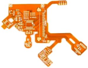
Polyimide PCBs
Polyimide PCBs are specialized circuit boards made from polyimide materials, which are known for their heat resistance and flexibility. These boards are often used in situations where standard PCBs, such as those made from FR4, cannot perform due to temperature, flexibility, or weight constraints. Polyimide PCBs are especially valuable in sectors requiring durability in extreme conditions, like aerospace, automotive, and wearables.
But here’s the kicker: polyimide’s ability to withstand extreme heat and its flexible nature make it the ideal choice for high-performance applications. This article will explore why polyimide PCBs have become essential in some of the most demanding industries and why they continue to grow in popularity.
Polyimide PCBs are made by coating a polyimide film with copper and then etching the desired circuit pattern. They are lightweight, resistant to high temperatures, and can be used in flexible circuit designs, making them an invaluable asset for many modern technological products.
Table 1: Key Properties of Polyimide PCBs
| Property | Description | Impact on PCB Performance |
|---|---|---|
| High Temperature Resistance | Ability to withstand high temperatures (up to 250°C) | Ideal for high-performance electronics |
| Flexibility | Can bend and conform to tight spaces | Essential for wearable tech and flexible circuits |
| Durability | Resistant to chemical exposure and mechanical stress | Extends the life of devices in harsh conditions |
Polyimide PCBs are unique primarily due to the material they are made from: polyimide, a high-performance polymer. Polyimide’s chemical structure makes it an excellent insulator with high thermal stability and low moisture absorption. These properties make polyimide ideal for applications where standard PCBs may fail.
Ready for the good part? Polyimide boards are lightweight yet durable, offering the perfect combination of flexibility and performance for demanding environments. Unlike standard FR4, polyimide’s high glass transition temperature (Tg) allows it to maintain its structural integrity even at high temperatures, making it the go-to material for aerospace and automotive applications.
Polyimide’s ability to withstand thermal cycling and mechanical stress ensures that polyimide PCBs perform reliably in environments where other materials may fail, making them an invaluable choice for industries like aerospace, defense, automotive, and electronics.
Table 2: Comparison Between Polyimide and FR4 PCBs
| Property | Polyimide PCB | FR4 PCB |
|---|---|---|
| Thermal Resistance | Can handle temperatures up to 250°C | Limited to ~130°C |
| Flexibility | Highly flexible and bendable | Rigid and stiff |
| Durability | Resistant to high-stress conditions | Less durable in extreme conditions |
Polyimide PCBs are fabricated using a multi-step process that includes the preparation of polyimide film, coating with copper, etching, and curing. But here’s the kicker: the process of manufacturing polyimide PCBs is more intricate than traditional FR4 PCBs because of the specialized materials used and the need for precision in design.
First, polyimide film is prepared and coated with a thin layer of copper. Then, the design is transferred onto the film using photolithography, where light-sensitive chemicals are applied, and the desired circuit patterns are etched. After the pattern is created, the polyimide film is cured, locking the copper in place and ensuring the board’s structural integrity.
Next, vias are created through laser drilling, allowing for the connection of different layers of the PCB. This is especially important in multi-layer polyimide PCBs used for high-density applications. Finally, the pads are prepared for component mounting, and the entire board is inspected to ensure it meets quality standards.
Table 3: Polyimide PCB Manufacturing Process
| Step | Description | Equipment Used |
|---|---|---|
| Polyimide Film Preparation | Coating the film with copper | Coating machines |
| Photolithography | Transfer of design onto polyimide film | UV exposure machines |
| Etching | Removing unwanted copper to form the circuit pattern | Chemical etching tanks |
| Drilling and Vias Creation | Laser drilling for vias and interconnections | Laser drilling systems |
| Curing and Inspection | Curing the polyimide and inspecting the board | Oven curing, AOI systems |
Polyimide PCBs offer several advantages, making them ideal for specific applications that demand high performance. What’s the real story? Polyimide’s ability to maintain high performance under extreme conditions, combined with its flexibility, makes it a superior choice for industries like aerospace, medical devices, and consumer electronics.
One of the biggest advantages of polyimide PCBs is their thermal stability. They can withstand high temperatures (up to 250°C) without degrading or losing functionality. This is essential for devices that operate in high-heat environments, such as automotive or industrial machinery.
Another advantage is flexibility. Polyimide PCBs can be made into flexible circuits that can bend and conform to tight spaces, which is a major benefit for wearable devices and flexible displays. These boards are also lightweight, which is a critical factor in industries where reducing weight is essential, such as aerospace and automotive.
Polyimide PCBs also provide enhanced electrical performance, as they have lower dielectric loss and greater insulation properties than traditional PCBs. This makes them ideal for high-frequency applications, such as telecommunications and signal processing.
Table 4: Benefits of Polyimide PCBs
| Benefit | Description | Applications |
|---|---|---|
| High-Temperature Resistance | Withstands temperatures up to 250°C | Automotive, aerospace |
| Flexibility | Can be bent and used in flexible applications | Wearables, flexible displays |
| Enhanced Electrical Performance | Low dielectric loss and high insulation | Telecommunications, medical devices |
Polyimide PCBs are used across a wide range of industries due to their superior properties. Ready for the good part? These boards are designed for high-performance applications that require high heat resistance, flexibility, and reliability.
In aerospace, polyimide PCBs are used in flight control systems, satellite electronics, and other high-altitude applications where temperature fluctuations and weight are critical considerations. Polyimide’s thermal stability and lightweight nature make it ideal for these high-demand environments.
In the automotive industry, polyimide PCBs are used in engine control units, sensors, and other critical automotive systems. These PCBs are designed to withstand the extreme heat and vibrations that are common in automotive environments.
Wearable electronics, such as smartwatches, fitness trackers, and medical devices, often use polyimide PCBs because of their flexibility. These devices require PCBs that can bend and fit into compact spaces while still providing reliable performance. Polyimide’s ability to handle flexible designs makes it an essential material for these applications.
Table 5: Key Applications of Polyimide PCBs
| Industry | Application | Key Features |
|---|---|---|
| Aerospace | Flight control systems, satellites | High temperature resistance, lightweight |
| Automotive | Sensors, engine control units | Thermal stability, durability |
| Wearable Electronics | Smartwatches, fitness trackers | Flexibility, small form factor |
Polyimide and FR4 are two of the most commonly used materials for PCBs. But here’s the kicker: while FR4 is cost-effective and works well in most standard applications, polyimide outperforms it in high-temperature and flexible environments.
FR4 is made from fiberglass and epoxy resin and is ideal for standard, rigid PCBs used in consumer electronics and computers. However, it has a relatively low glass transition temperature (Tg) of around 130°C, making it unsuitable for high-temperature environments.
On the other hand, polyimide can withstand temperatures up to 250°C, making it the preferred material for high-performance applications like aerospace and automotive systems. Polyimide also offers better flexibility, which is essential for wearable devices and flexible circuits.
Table 6: Polyimide PCB vs. FR4 PCB
| Property | Polyimide PCB | FR4 PCB |
|---|---|---|
| Temperature Resistance | Up to 250°C | Up to 130°C |
| Flexibility | Highly flexible | Rigid |
| Durability | High resistance to mechanical stress | Standard durability |
| Cost | More expensive | Cost-effective |
Polyimide PCBs are often used in high-density applications, where space is limited and performance is critical. What’s the real story? Polyimide’s ability to support high-density interconnections and flexible designs makes it the perfect choice for advanced electronics.
In high-density interconnect (HDI) applications, polyimide allows for smaller vias and higher-density circuits without compromising on performance. HDI PCBs are essential in devices like smartphones, tablets, and other compact, high-performance electronics.
The ability to create flexible circuits using polyimide is another reason why it’s preferred for high-density applications. Flexible polyimide PCBs can be bent to fit into compact spaces, such as wearables, and still maintain high-performance standards.
Table 7: Polyimide PCBs in High-Density Applications
| Application Type | Benefit | Key Features |
|---|---|---|
| HDI Applications | Higher density, smaller vias | Supports advanced electronic devices |
| Flexible Circuits | Space-efficient, bendable designs | Ideal for wearable and portable electronics |
Designing polyimide PCBs involves more than just choosing the right material. Ready for the good part? Understanding the specific design challenges and best practices for polyimide PCBs is crucial for ensuring a successful product.
When designing polyimide PCBs, one key consideration is pad design. Pads must be large enough to accommodate solder joints but not so large as to cause excess solder or bridging. The design also needs to account for thermal management, as polyimide PCBs are often used in high-temperature applications. Thermal vias and proper heat dissipation routes are critical to ensure the board doesn’t overheat during operation.
Table 8: Design Tips for Polyimide PCBs
| Design Tip | Consideration | Benefit |
|---|---|---|
| Pad Design | Ensure pads are appropriately sized | Improves solder joint quality |
| Thermal Management | Use thermal vias and copper pours | Ensures proper heat dissipation |
| Component Placement | Optimize layout for space and performance | Maximizes space efficiency and reliability |
Despite its many advantages, polyimide PCB manufacturing comes with its own set of challenges. Ready for the kicker? Overcoming these challenges is essential for ensuring the high performance and reliability of polyimide PCBs in demanding environments.
One common challenge is adhesion. Polyimide’s unique properties can make it difficult to bond with other materials, especially during multi-layer PCB manufacturing. To overcome this, special surface treatments are often applied to enhance adhesion.
Material costs can also be a concern, as polyimide is more expensive than traditional PCB materials like FR4. However, the higher cost is often justified by the enhanced performance and reliability that polyimide provides in critical applications.
Table 9: Challenges in Polyimide PCB Manufacturing
| Challenge | Solution | Impact on Manufacturing |
|---|---|---|
| Adhesion Issues | Use surface treatments to improve bonding | Enhances multi-layer PCB performance |
| High Material Costs | Optimize design for cost-efficiency | Balances cost with performance |
| Process Complexity | Specialized equipment and techniques required | Increases manufacturing time and cost |
Polyimide PCBs have proven themselves to be a vital material in many high-performance and flexible electronic devices. Whether for aerospace, automotive, wearables, or medical devices, polyimide’s unique combination of flexibility, high-temperature resistance, and electrical performance makes it the material of choice for a wide range of industries. Ready for the good part? As the demand for more compact and durable electronic devices grows, polyimide PCBs will continue to be at the forefront of advanced electronics, offering a solution that balances performance, reliability, and flexibility.and flexible circuit applications. However, polyimide is more expensive than FR4.
Polyimide PCBs are often used in mission-critical applications, so ensuring their reliability through rigorous testing is paramount. Ready for the kicker? The testing phase for polyimide PCBs is just as essential as the manufacturing process itself. These PCBs must undergo various tests to ensure they meet the required performance and quality standards before they are integrated into final products.
Testing begins with visual inspections, which are often automated and conducted to ensure that the pads, traces, and vias are properly aligned and there are no obvious defects such as delamination or improper etching. Following that, in-circuit testing (ICT) checks the electrical connections and ensures that all pads and traces are electrically conductive. For high-frequency applications, high-speed testing might also be conducted to ensure that the signal integrity is maintained.
One of the most critical aspects of testing polyimide PCBs is thermal cycling. Given that polyimide PCBs are often used in high-temperature environments, testing how they perform under temperature variations ensures they can handle the thermal stresses they will face during use. X-ray inspection is another useful technique, especially when examining multi-layer polyimide PCBs, to check for hidden defects in the vias and layers.
Table 10: Common Testing Methods for Polyimide PCBs
| Testing Method | Description | Benefits |
|---|---|---|
| Visual Inspection | Automated inspection to detect defects | Quick and cost-effective |
| In-Circuit Testing | Measures electrical continuity | Ensures proper connectivity |
| High-Speed Testing | Tests for signal integrity in high-frequency circuits | Validates high-speed performance |
| Thermal Cycling | Simulates temperature fluctuations to test thermal stability | Ensures thermal reliability |
| X-Ray Inspection | Inspects internal layers and vias | Detects hidden defects in multi-layer designs |
Polyimide PCBs are typically more expensive than standard FR4 PCBs. What’s the real story? The higher cost is primarily due to the advanced materials used and the specialized manufacturing processes required. While polyimide offers significant advantages in performance and durability, businesses must evaluate whether these benefits justify the added cost, especially for high-volume production.
The cost of polyimide PCBs is influenced by several factors, including material selection, complexity of the design, and volume of production. For instance, high-density polyimide PCBs with multiple layers will be more expensive than simpler, single-layer designs. Additionally, the cost of polyimide material itself is higher than that of traditional materials like FR4, contributing to the overall price.
Another factor that affects cost is the complexity of the manufacturing process. Polyimide PCBs often require more precision in the design and etching process due to the material’s unique properties. Additionally, specialized equipment is needed for processes like laser drilling and multi-layer integration, which adds to the cost of production.
However, the added cost of polyimide PCBs can be justified when the applications require high-temperature resistance, flexibility, and durability. Industries like aerospace, automotive, and medical devices rely on these performance qualities, where reliability and long-term durability are crucial.
Table 11: Factors Affecting the Cost of Polyimide PCBs
| Factor | Impact on Cost | Example Application |
|---|---|---|
| Material Selection | Polyimide is more expensive than standard PCB materials | Aerospace, automotive |
| Design Complexity | Complex designs with multi-layer boards increase cost | Medical devices, high-performance electronics |
| Volume of Production | Larger production runs reduce per-unit cost | Consumer electronics, automotive |
| Manufacturing Process | Requires specialized equipment and precision | High-density interconnects, flexible designs |
Designing polyimide PCBs requires careful attention to detail, as the material has unique properties that influence both its electrical and mechanical performance. Ready for the good part? The following design best practices will help ensure your polyimide PCB performs optimally and meets all reliability and performance standards.
Pad design is one of the most critical aspects of polyimide PCB design. The pads must be sized correctly to ensure proper solder joints and avoid issues such as cold soldering. Thermal vias are also important for managing heat dissipation. Polyimide’s thermal conductivity should be accounted for in the design to ensure efficient heat flow.
Another essential design consideration is the layout of traces and components. Given the flexibility of polyimide, it is essential to ensure that the layout accommodates bending and flexing, especially in flexible circuit applications. Proper trace width is necessary to ensure reliable electrical connections, and adequate spacing must be maintained to avoid short circuits or signal interference.
Finally, layer stacking is important when designing multi-layer polyimide PCBs. Polyimide’s unique properties allow for higher-density circuits, but it’s important to ensure proper alignment and layer separation to maintain electrical and mechanical integrity.
Table 12: Design Best Practices for Polyimide PCBs
| Design Element | Best Practice | Benefit |
|---|---|---|
| Pad Design | Ensure pads are appropriately sized and aligned | Maximizes solder joint quality |
| Thermal Management | Use thermal vias and copper pours to manage heat | Prevents overheating and extends device life |
| Trace Width | Optimize trace width for conductivity and signal integrity | Ensures reliable electrical connections |
| Layer Stacking | Ensure proper alignment of multi-layer designs | Maintains electrical and mechanical stability |
Polyimide PCB technology is constantly evolving, with new materials and techniques emerging to meet the growing demands of modern electronics. What’s the real story? As devices become smaller and more powerful, the role of polyimide PCBs in these innovations continues to grow. Let’s take a look at some of the trends shaping the future of polyimide PCB technology.
One exciting trend is the development of 3D-printed polyimide PCBs. 3D printing allows for more intricate and customized PCB designs, which could revolutionize the way polyimide PCBs are produced. This technology offers faster prototyping and reduced lead times, making it easier to test new designs and improve product development cycles.
Another trend is the integration of polyimide with other materials. Researchers are exploring the combination of polyimide with graphene, carbon nanotubes, and other advanced materials to enhance the conductivity and mechanical properties of the PCBs. These materials offer the potential to increase the performance of polyimide PCBs in high-frequency applications and extreme environments.
Finally, the growth of flexible and wearable electronics continues to drive demand for flexible polyimide PCBs. As consumer electronics become more integrated into daily life, the need for lightweight, flexible, and durable components is increasing, making polyimide PCBs even more critical for future innovations.
Table 13: Emerging Trends in Polyimide PCB Technology
| Trend | Description | Potential Impact |
|---|---|---|
| 3D-Printed Polyimide PCBs | Using 3D printing technology for faster prototyping and customized designs | Speeds up product development cycles |
| Polyimide with Advanced Materials | Combining polyimide with graphene and carbon nanotubes for improved conductivity | Enhances performance in high-frequency applications |
| Flexible and Wearable Electronics | Increased demand for flexible, durable PCBs in wearable technology | Drives innovation in consumer electronics and healthcare |
In conclusion, polyimide PCBs are an essential component in modern electronics, offering unmatched benefits in terms of temperature resistance, flexibility, and durability. Ready for the kicker? As technology continues to advance, polyimide PCBs will play a pivotal role in the development of next-generation electronics, from flexible wearables to high-performance aerospace systems. Understanding the benefits, manufacturing processes, and design considerations of polyimide PCBs is crucial for businesses involved in electronics manufacturing. By leveraging polyimide technology, companies can ensure that their products meet the highest standards of performance and reliability in the most demanding applications.
FAQ Section
Q1: What is a polyimide PCB?
A1: A polyimide PCB is a type of printed circuit board made from polyimide material, known for its heat resistance and flexibility. These boards are used in high-performance applications such as aerospace, medical devices, and wearable electronics.
Q2: How does the polyimide PCB manufacturing process work?
A2: The polyimide PCB manufacturing process involves applying a polyimide film to copper, then transferring the design using photolithography. The board is etched, drilled, and cured, creating a durable and flexible circuit that can withstand extreme conditions.
Q3: What are the benefits of polyimide PCBs?
A3: Polyimide PCBs offer several advantages, including high-temperature resistance, flexibility, durability, and enhanced electrical performance. These benefits make them ideal for applications in aerospace, automotive, medical devices, and wearable technology.
Q4: How do polyimide PCBs compare to FR4 PCBs?
A4: Polyimide PCBs are more heat-resistant and flexible than FR4 PCBs, making them better suited for high-temperature and flexible applications. However, they are typically more expensive than FR4, which is more cost-effective for general use.
Q5: What industries use polyimide PCBs?
A5: Polyimide PCBs are used in industries such as aerospace, automotive, medical devices, wearables, and high-density electronics. They are ideal for applications requiring high performance, flexibility, and durability.


Connect to a Jerico Multilayer PCB engineer to support your project!
Request A Quote


 Quote
Quote