


+86 13603063656
Rigid PCBs (Printed Circuit Boards) are essential to the electronic industry, providing the foundation for almost every electronic device we use today. From consumer electronics to industrial machinery, these rigid boards ensure that our devices perform efficiently. In this article, we will explore the benefits, design considerations, and various applications of rigid PCBs, providing a comprehensive understanding of how these components drive modern technology.
Rigid PCB
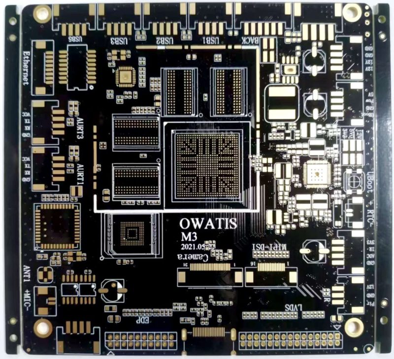
A rigid PCB is a type of printed circuit board that uses a solid, inflexible base to support its electrical components and connections. These boards are made from materials that are strong enough to maintain their shape under different environmental conditions, such as heat, humidity, and mechanical stress. The rigid nature of these boards makes them highly reliable and durable, which is why they are the most commonly used type of PCB in various industries.
What’s the real story? Without rigid PCBs, modern electronic devices would not function as reliably or efficiently. The versatility and reliability of rigid PCBs make them a cornerstone of the electronics industry, supporting everything from simple consumer gadgets to complex medical devices.
| Type | Description | Use Case |
|---|---|---|
| Single-Sided PCB | Components mounted on one side of the board | Basic electronics such as toys or LED displays |
| Double-Sided PCB | Components mounted on both sides of the board | More complex devices such as computers or smartphones |
| Multi-Layer PCB | Multiple layers of conductive traces for complex designs | High-performance applications like automotive and telecommunications |
Rigid PCBs consist of several essential components that work together to provide both mechanical and electrical stability. These components include the substrate, copper traces, solder mask, silkscreen, and components like resistors and capacitors. The substrate, usually made of materials like FR4, acts as the solid base that holds the entire structure together.
The substrate material is the foundation of the rigid PCB and determines the board’s mechanical strength and thermal properties. The most common material used for rigid PCBs is FR4, a type of fiberglass epoxy laminate. Other materials, like metal core and high-frequency substrates, may be used for specialized applications.
Copper traces are the conductive paths on the PCB that connect the components. These traces are etched from copper foil using a chemical process. The design and thickness of the traces are crucial, as they need to handle the electrical current without overheating or causing signal interference.
The solder mask is a protective layer applied to the PCB to prevent accidental short circuits during assembly. The silkscreen layer is used to print text and symbols onto the board to help with component placement during assembly.
But here’s the kicker… The components and materials used in rigid PCBs must be carefully selected based on the specific requirements of the final product, as the board’s performance depends on it.
| Component | Description | Role in PCB Design |
|---|---|---|
| Substrate | A solid base material, usually FR4 | Provides mechanical strength and thermal stability |
| Copper Traces | Conductive pathways on the board | Facilitates electrical connections between components |
| Solder Mask | Protective coating on the PCB | Prevents solder bridges and short circuits |
| Silkscreen | Printed text and symbols on the board | Helps with component placement during assembly |
Rigid PCBs are available in various forms, each suited to different applications and design needs. The most common types of rigid PCBs include single-sided, double-sided, and multi-layer boards. Each type has its unique features and is selected based on the complexity of the circuit design.
Single-sided PCBs are the simplest and most cost-effective type of rigid PCB. These boards feature a single layer of copper traces on one side of the board, with components mounted only on that side. They are commonly used in low-complexity electronic devices like toys, LED lights, and simple power supplies.
Double-sided rigid PCBs have copper traces on both sides of the board, with components mounted on both sides as well. These boards provide more room for components and are used in more complex circuits, such as those found in computers, smartphones, and automotive systems.
Multi-layer rigid PCBs are the most complex type, consisting of multiple layers of conductive material. These boards are ideal for high-performance applications that require high-density interconnections and better signal integrity. They are used in applications like telecommunications, medical devices, and advanced computing systems.
This is where it gets interesting… The type of rigid PCB you choose depends on the complexity of your design and the performance requirements of your device. While single-sided boards are sufficient for simple circuits, multi-layer boards are necessary for high-performance applications that require compact designs.
| Type | Characteristics | Ideal Use Case |
|---|---|---|
| Single-Sided PCB | Simple design, one side of copper and components | Basic electronic devices like toys or household appliances |
| Double-Sided PCB | Two sides for components and traces | Intermediate complexity devices like smartphones or small computers |
| Multi-Layer PCB | Multiple layers of traces for complex designs | High-density circuits in telecommunications, medical devices, and computers |
The process of manufacturing a rigid PCB involves several key steps, each designed to ensure the final board meets all functional and mechanical specifications. These steps include material preparation, copper etching, drilling, and component placement. Here’s a closer look at the overall process.
The first step in PCB manufacturing is selecting the right materials. Typically, a copper-clad laminate is used for the PCB substrate. This laminate is prepared by applying a layer of copper foil to the substrate, which will later be etched to form the circuit pattern.
After the material is prepared, the next step is etching the copper foil to form the circuit paths. A chemical process is used to remove the excess copper, leaving behind the desired conductive traces. For multi-layer PCBs, this process is repeated for each layer.
Once the layers are prepared, holes are drilled into the board to allow components to be placed and vias (small holes that connect different layers) to be formed. The size and placement of these holes are critical for the overall performance of the PCB.
The final step in PCB manufacturing is the placement of electronic components on the board. The components are soldered onto the board, either manually or using automated pick-and-place machines, and the board is tested for functionality.
What’s the real story? Every step of the manufacturing process is crucial for ensuring the final PCB is both functional and reliable. Errors in any phase can lead to costly delays and product failures.
| Step | Description | Importance |
|---|---|---|
| Material Preparation | Preparing the copper-clad laminate substrate | Ensures the foundation of the PCB is correct |
| Etching and Layering | Removing excess copper to form traces and layers | Defines the conductive paths and circuit structure |
| Drilling and Via Formation | Creating holes for components and vias | Enables component placement and layer connectivity |
| Component Placement and Soldering | Placing and soldering components onto the board | Finalizes the PCB and makes it functional |
Rigid PCBs offer several advantages that make them the preferred choice for many electronic applications. These advantages include durability, cost-effectiveness, and the ability to support complex circuit designs.
Rigid PCBs are designed to withstand environmental stressors such as temperature fluctuations, mechanical stress, and vibrations. This makes them ideal for use in demanding industries like automotive, aerospace, and industrial automation.
Rigid PCBs are capable of handling high-speed signals and high-current circuits, making them suitable for high-performance applications such as medical devices and telecommunications. Their design allows for efficient power distribution and signal integrity.
For large-scale production, rigid PCBs are cost-effective due to their simpler design compared to flexible PCBs. Mass production techniques can be used to reduce manufacturing costs, making rigid PCBs a popular choice for consumer electronics.
This is where it gets interesting… Despite their advantages, rigid PCBs have limitations, particularly in terms of flexibility and form factor. But for most applications, these boards provide the perfect balance of durability, cost, and performance.
| Advantage | Description |
|---|---|
| Durability and Reliability | Resistant to environmental stressors like temperature and vibration |
| High Performance | Suitable for high-speed and high-current applications |
| Cost-Effectiveness | Cost-effective for mass production |
The materials used in rigid PCBs play a crucial role in determining their performance, durability, and cost. The most common material used in rigid PCBs is FR4, a type of fiberglass, but other materials like metal core and high-frequency laminates are used for specialized applications.
FR4 is the most commonly used material for rigid PCBs. It is a strong, durable, and cost-effective option that offers good electrical insulation properties. FR4 boards are used in a wide variety of applications, from consumer electronics to automotive systems.
For high-speed or high-frequency applications, materials like PTFE (polytetrafluoroethylene) and Rogers laminates are used. These materials have excellent dielectric properties that ensure signal integrity and reduce losses at higher frequencies.
In applications requiring superior heat dissipation, metal core PCBs are used. These boards have a metal base layer (usually aluminum) that helps dissipate heat more efficiently, making them ideal for power electronics and LED lighting systems.
What’s the real story? The material you choose for your rigid PCB will impact its performance, cost, and suitability for specific applications. It’s essential to select the right material based on your design requirements.
| Material | Characteristics | Ideal Applications |
|---|---|---|
| FR4 | Durable, cost-effective, and commonly used | General-purpose PCBs for consumer electronics |
| PTFE | Excellent dielectric properties for high-frequency use | RF and high-speed applications |
| Metal Core | Superior heat dissipation due to metal substrate | Power electronics, LED lighting |
Designing a rigid PCB requires attention to detail to ensure that the board is both functional and manufacturable. Below are some key design tips to keep in mind when designing a rigid PCB.
Effective component placement is critical for a successful PCB design. Components should be placed to minimize signal interference and to ensure that the board can be easily assembled. It’s also important to leave adequate space around components for heat dissipation and proper routing.
Proper routing of electrical traces is essential for signal integrity and power distribution. Traces should be kept as short and direct as possible to reduce resistance and signal loss. Ground planes and power planes should also be included to improve performance.
Ensure that your design is easy to manufacture by considering factors such as trace width, component size, and the placement of vias. A well-optimized design will minimize errors and reduce manufacturing costs.
Ready for the good part? Following these design tips will ensure that your rigid PCB is both reliable and cost-effective, meeting the performance requirements for your device.
| Tip | Description |
|---|---|
| Component Placement | Place components with adequate spacing and alignment |
| Trace Routing | Use short, direct traces to minimize loss and interference |
| Manufacturability | Design with easy manufacturing in mind to reduce errors |
Testing and quality control are critical aspects of rigid PCB manufacturing. Rigorous testing ensures that the board meets its functional requirements and is free of defects.
Electrical testing is used to verify that all components are connected correctly and that there are no open circuits or short circuits. Methods like in-circuit testing (ICT) and flying probe testing are used to identify any electrical faults.
Mechanical testing ensures that the PCB can withstand physical stress, including bending, vibrations, and thermal cycling. This type of testing is particularly important for rigid PCBs used in automotive, aerospace, and industrial applications.
Rigid PCBs must meet various quality standards, such as ISO 9001 and IPC-2221, which ensure that the boards are designed and manufactured to high standards. Certification of compliance is essential for ensuring that the boards meet the required safety and reliability specifications.
This is where it gets interesting… With proper testing and quality control, you can ensure that your rigid PCBs meet the highest standards, minimizing the risk of defects and improving the overall performance of your devices.
| Testing Method | Description | Purpose |
|---|---|---|
| Electrical Testing | Verifies the electrical connections of the PCB | Detects open circuits, shorts, and other faults |
| Mechanical Testing | Tests the PCB’s ability to withstand physical stress | Ensures reliability in harsh environments |
| Quality Standards | Compliance with industry standards (ISO, IPC) | Guarantees product quality and reliability |
Rigid PCBs are used in a wide range of applications across different industries. From consumer electronics to industrial equipment, rigid PCBs play a crucial role in the functioning of modern devices.
Rigid PCBs are widely used in consumer electronics such as smartphones, tablets, and televisions. These devices require high-performance PCBs that are both reliable and cost-effective.
In the automotive and industrial sectors, rigid PCBs are used in control systems, sensors, and power electronics. These PCBs must meet stringent reliability standards to function effectively in demanding environments.
Rigid PCBs are also used in medical devices like diagnostic tools and pacemakers, where reliability and precision are essential. Additionally, they are used in telecommunications for signal processing and data transmission.
What’s the real story? The diverse range of applications for rigid-PCBs highlights their versatility and importance in today’s technological landscape.
| Industry | Application | Requirements |
|---|---|---|
| Consumer Electronics | Smartphones, TVs, gaming consoles | High performance and compact designs |
| Automotive | Control systems, sensors, power electronics | High reliability in demanding environments |
| Medical Devices | Diagnostic tools, pacemakers | Precision, reliability, and longevity |
Rigid-PCBs are essential components in modern electronics, offering durability, reliability, and performance. Whether in consumer electronics, industrial applications, or medical devices, these boards are crucial for ensuring that products function efficiently. As technology continues to evolve, rigid PCBs will remain a fundamental part of the electronics industry, enabling the development of more complex and advanced devices.
And now you know the full story on rigid-PCBs! From their design and materials to their various applications and benefits, rigid-PCBs are indispensable for the modern electronics industry.
Q1: What is a rigid-PCB?
A1: A rigid PCB is a type of printed circuit board that uses a solid, inflexible substrate to support electrical components and connections.
Q2: What are the benefits of using rigid-PCBs?
A2: Rigid PCBs are durable, reliable, and cost-effective, making them ideal for a wide range of applications that require stability and performance.
Q3: What materials are used in rigid PCBs?
A3: Common materials for rigid PCBs include FR4, a fiberglass epoxy laminate, as well as high-frequency materials like PTFE and metal core substrates for specialized applications.
Q4: How are rigid-PCBs tested for quality?
A4: Rigid PCBs undergo electrical and mechanical testing to ensure proper functionality and durability, with compliance to industry standards like ISO 9001 and IPC-2221.
Q5: What are the main applications of rigid-PCBs?
A5: Rigid PCBs are used in a variety of industries, including consumer electronics, automotive, medical devices, and telecommunications, where reliability and performance are critical.


Connect to a Jerico Multilayer PCB engineer to support your project!
Request A Quote


 Quote
Quote