


+86 13603063656
Printed Circuit Board (PCB) manufacturing has become a cornerstone of modern electronics, with increasingly tighter tolerances, more complex designs, and higher expectations for reliability. Among the many strategies employed to improve production efficiency and reliability, Reserved Process Edges have emerged as one of the most practical yet often underappreciated features.
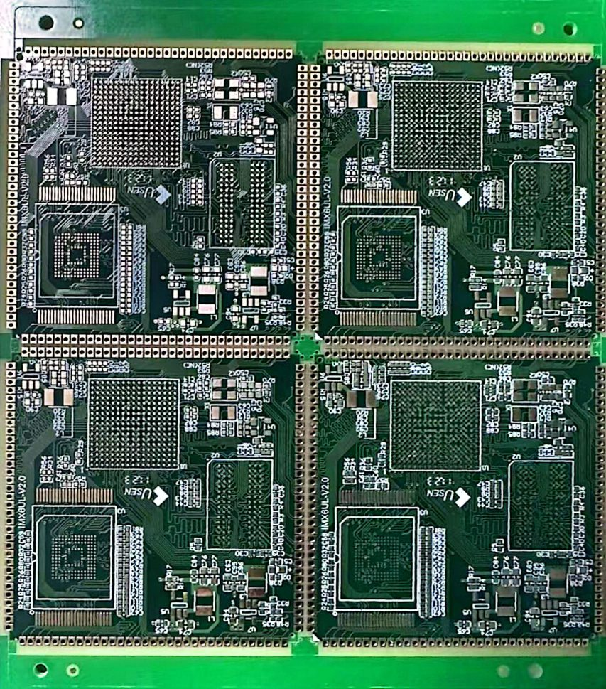
At its simplest, Reserved Process Edges refer to additional edge regions of a PCB panel that are deliberately set aside to facilitate handling, tooling, and processing during manufacturing. These zones typically do not contain functional circuitry but instead act as sacrificial or support areas that protect the main circuit during fabrication and assembly steps.
When manufacturers first began to experiment with Reserved Process Edges decades ago, they were motivated mainly by the need for better conveyor handling and soldering stability. Over time, however, the practice evolved into a deliberate engineering design choice that affects yield, cost, and product quality. Today, Reserved Process Edges are built into many CAD templates and are part of a standard design-for-manufacturing (DFM) checklist.

Reserved Process Edges
Modern PCBs often go through dozens of process steps — from lamination and drilling to plating, solder mask application, and final assembly. At each stage, the panel is subjected to mechanical handling, clamping, or conveyor movement. By adding Reserved Process Edges, manufacturers can:
Stabilize the panel during high-temperature or high-pressure steps.
Protect functional traces from chipping, solder splash, or edge cracking.
Provide space for tooling holes, fiducials, and barcodes without sacrificing usable area.
In short, Reserved Process Edges transform how a PCB interacts with the production environment. Although they may appear trivial, their impact on yield, cost, and reliability is considerable.
As a PCB manufacturing observer, I see Reserved Process Edges as emblematic of a larger trend: subtle design interventions that dramatically improve the production process without requiring exotic materials or expensive equipment. Many organizations focus on headline technologies like HDI or additive manufacturing, but Reserved Process Edges demonstrate how incremental, low-cost changes can deliver major gains.
The concept of Reserved Process Edges can be unpacked into several layers: the physical definition, the design intent, the manufacturing rationale, and the performance implications. This section provides a detailed look at each.
Reserved Process Edges are non-functional perimeter strips that run along one or more sides of a PCB panel. These strips are deliberately left free of electrical components or critical copper features so they can be used for:
Tooling holes that align layers during lamination.
Breakaway tabs or rails that allow post-assembly depanelization.
Conveyor fingers or mechanical grippers during automated assembly.
Test coupons or control structures for process monitoring.
Most commonly, Reserved Process Edges range from 5 mm to 15 mm in width, but the exact dimension depends on board size, panelization strategy, and assembly equipment.
From a design perspective, these edges may be added as “rails” in CAD software. From a production standpoint, they form an integral part of the panel outline.
Historically, PCBs were smaller, less dense, and often handled manually. The need for Reserved Process Edges was therefore limited. As manufacturing volumes grew and pick-and-place equipment became dominant, it became clear that extra handling areas were essential to prevent damage.
By the early 2000s, major PCB assemblers had established design rules recommending Reserved Process Edges for virtually all medium- and high-volume production runs. Today, many industry standards, including IPC guidelines, explicitly or implicitly reference edge clearance and tooling zones.
While Reserved Process Edges may seem similar to other edge practices, such as chamfering or edge plating, their purpose and design criteria are distinct:
| Feature | Reserved Process Edges | Edge Chamfering | Edge Plating |
|---|---|---|---|
| Primary Goal | Handling & process stability | Mechanical fit (e.g., card edge connectors) | Electrical continuity or shielding |
| Copper Presence | Typically none in critical areas | May include copper pads | Copper extends to edge or wraps around |
| Post-Process Fate | Often removed or depanelized | Remains part of finished board | Remains part of finished board |
This distinction matters because Reserved Process Edges are a process aid, not a functional requirement of the end product.
Reserved Process Edges are closely linked to panelization — the practice of arranging multiple PCB units on a larger panel for efficiency. Typical methods include V-scoring and mouse bites (tab-routing). Reserved Process Edges often serve as the main structural rails that keep the panel rigid until final depanelization.
By integrating Reserved Process Edges with panelization features, manufacturers can ensure:
Reduced warpage during soldering.
Simplified depanelization with minimal stress on finished circuits.
Room for fiducials, which improve automated optical inspection accuracy.
Reserved Process Edges embody a principle of “designing for the process, not just the product.” By thinking ahead to how a board will be built, designers and process engineers cooperate to create a manufacturing flow that is both more efficient and less error-prone. This holistic view is increasingly important as PCBs become denser and margins for error shrink.
When incorporating Reserved Process Edges into a design, engineers must decide how much non-functional area to allocate, what mechanical features to include, and how the edges will interact with panelization. Common design choices include:
Width of the Reserved Process Edges: Typically between 5 mm and 15 mm, chosen to match assembly equipment.
Tooling and Fiducial Placement: Designers often locate tooling holes, fiducials, and barcodes on these edges, ensuring that functional areas remain untouched.
Conveyor Contact Zones: For SMT processes, these edges provide secure zones for conveyor fingers to grip without damaging pads or components.
Good design practice also involves annotating these edges clearly in CAD files so that manufacturing partners know which areas are sacrificial and which are functional.
Reserved Process Edges are usually fabricated from the same base laminate as the PCB itself, which helps maintain dimensional stability during heating and cooling cycles. However, because they may be cut away later, tolerances can be somewhat looser.
Tolerances: ±0.2 mm is common for edge-to-feature distances.
Material: FR-4 for standard boards, but also polyimide or high-Tg laminates for high-temperature applications.
Solder Mask and Surface Finish: Typically non-critical, though some manufacturers add solder mask clearance for fiducials or test pads.
By keeping material and process continuity between the Reserved Process Edges and the main board, designers ensure predictable behavior during lamination and soldering.
Reserved Process Edges and panelization go hand in hand. By designing proper rails, mouse bites, or V-scores along these edges, manufacturers can depanelize boards cleanly with minimal stress. For example, a board with high-density BGAs may be especially sensitive to flexing; robust Reserved Process Edges provide the extra rigidity needed during assembly.
Some designers even incorporate test coupons or impedance structures directly into these edges so they can monitor process consistency without taking space from the main circuitry.
From my point of view, the real power of Reserved Process Edges lies in how they shift thinking from “how the PCB should look” to “how the PCB should be built.” This is the essence of Design for Manufacturability (DFM). When process engineers have guaranteed handling zones, they can optimize assembly line speed, reduce defect rates, and avoid costly design modifications after prototypes.
In other words, Reserved Process Edges are not merely a layout detail — they are a communication channel between designers and manufacturers.
One of the most important benefits of Reserved Process Edges is yield improvement. PCBs are susceptible to edge-related defects during fabrication and assembly, such as solder bridging, pad chipping, or trace cracking. By including Reserved Process Edges:
Mechanical Stress is Absorbed by Sacrificial Areas: Instead of cracking functional traces, the stress dissipates through the Reserved Process Edges.
Fewer Handling Defects: Automated assembly equipment can grip non-functional rails, reducing risk to actual circuitry.
Improved Alignment: Tooling holes on Reserved Process Edges provide consistent registration between layers, reducing misalignment defects.
These improvements translate directly into higher first-pass yield, which is crucial for cost-sensitive or high-volume production.
Many PCB assemblers have published case studies showing that adding Reserved Process Edges can reduce defect rates by 20–40% depending on board complexity. For example:
A consumer electronics manufacturer introduced 10 mm Reserved Process Edges on smartphone boards and reduced conveyor drop defects by 25%.
An automotive PCB plant achieved a 15% improvement in solder joint quality by adding Reserved Process Edges to their control boards, stabilizing them during wave soldering.
These are not isolated incidents but part of a broader pattern.
Yield and cost are intimately linked. Every time a board is scrapped or reworked, money is lost. By introducing Reserved Process Edges:
Fewer Scrap Boards: Higher first-pass yield means fewer defective boards.
Reduced Rework Labor: Less touch-up work after soldering or assembly.
Optimized Panel Utilization: Better edge stability allows tighter spacing between boards, maximizing the number of units per panel.
These effects may seem incremental individually, but across thousands of boards they translate to substantial savings.
One of the most immediate ways Reserved Process Edges cut costs is by optimizing panel utilization. When PCBs are arrayed on a panel, the stability provided by Reserved Process Edges lets engineers position boards closer together. This means more usable circuits per panel and less laminate discarded.
In many manufacturing environments, a 2–3 mm reduction in spacing multiplied across dozens of PCBs can equate to a 5–10% material saving. Over the course of a production run of hundreds of thousands of units, that adds up to a major cost advantage.
Reserved Process Edges give process engineers a reliable area to place tooling holes, alignment pins, and fiducials. Tooling plates can be standardized because the edge rails provide predictable registration points. This reduces the number of unique jigs needed for different board designs.
Furthermore, because assembly machines can grab the panel consistently, line operators spend less time adjusting conveyor widths or pick-and-place coordinates between jobs. The cumulative effect is lower labor cost and fewer stoppages.
Boards damaged during assembly or testing not only incur direct costs but also risk damaging customer relationships. Reserved Process Edges act as a sacrificial shield. Scratches, dents, or solder splashes often land on the non-functional edges instead of the circuitry. This lowers the rework rate and improves outgoing quality metrics.
A lower defect rate also means fewer warranty claims, fewer RMAs, and more predictable profit margins.
In my view, Reserved Process Edges epitomize a “hidden cost-saver.” Instead of negotiating cheaper materials or reducing quality, companies can design smarter to save money. This is a long-term strategy that not only improves financial metrics but also raises the technical sophistication of the manufacturing process.
For organizations serious about cost reduction without sacrificing quality, JM PCB offers panel design consultation and manufacturing expertise, especially in integrating Reserved Process Edges. They can advise on optimal rail widths, tooling placement, and panelization strategies to maximize yield and minimize waste. Their experience with both high-volume consumer boards and high-reliability aerospace boards makes them an attractive partner for a wide range of industries.
Modern pick-and-place machines operate at high speed, relying on precise X–Y positioning and consistent conveyor grip. Reserved Process Edges provide non-critical rails for the machine to hold, preventing vibration or shifting during component placement.
This stability reduces placement error rates, especially for fine-pitch components such as 0.4 mm BGAs or tiny passive arrays. Fewer misplacements mean less rework and better first-pass yield.
During soldering, thermal expansion can cause warping, especially in thin or high-layer-count boards. Reserved Process Edges help maintain panel rigidity, reducing the “oil canning” effect that leads to uneven solder joints.
In wave soldering, the conveyor fingers typically support the board only at its edges. By using Reserved Process Edges, designers ensure these contact points lie outside the functional area, protecting solder masks and copper features from mechanical wear.
AOI (Automated Optical Inspection) machines also benefit from Reserved Process Edges. Fiducials placed on these edges improve the accuracy of vision systems. Moreover, if a panel needs to be flipped or rotated during inspection, the sacrificial edges provide gripping zones for robotic arms.
This reduces the chance of smudging solder paste or damaging small components after reflow.
Every second saved in a high-volume assembly line adds up. Reserved Process Edges reduce the need to slow down conveyors to handle delicate boards. With better mechanical stability, line speeds can be increased slightly without sacrificing quality.
This gain is modest on a per-board basis but significant across millions of units. In some factories, the ability to run lines just 5% faster translates to hundreds of thousands of extra boards per year. The power of Reserved Process Edges is how they align the needs of automated equipment with the constraints of PCB layout. They essentially act as a bridge: designers carve out sacrificial space so machines can do their job better. This synergy between human design and robotic execution defines modern electronics manufacturing.
Industries such as aerospace and automotive impose exceptionally strict reliability and safety standards. Here, Reserved Process Edges are not just optional — they are often a requirement.
Aerospace PCBs: Avionics boards are subjected to vibration, thermal cycling, and harsh environmental conditions. Reserved Process Edges provide the extra mechanical support needed during manufacturing and inspection so that sensitive traces remain untouched.
Automotive PCBs: Control modules, radar systems, and power electronics require robust solder joints and minimal contamination. Reserved Process Edges ensure conveyor fingers and tooling holes are placed away from critical areas, reducing contamination risk.
Boards destined for high-reliability environments often use thick copper, multiple layers, and exotic substrates. All of these factors increase the risk of edge cracking during assembly. Reserved Process Edges function as sacrificial “shock absorbers,” reducing stress concentrations at the boundaries of the functional circuit area.
This is especially important when depanelizing after reflow, because the combination of temperature, tension, and bending can easily fracture delicate interconnects if no sacrificial edge exists.
High-reliability sectors typically mandate 100% electrical testing and sometimes even X-ray inspection. Reserved Process Edges create more space for test pads, coupons, and alignment features. As a result, test fixtures can make better contact and yield more consistent results.
In my own analysis, this is one of the understated advantages of Reserved Process Edges: they improve the reliability not only of the board itself but also of the verification processes used to qualify it.
Medical implants and defense systems share the same need for consistency and traceability. Reserved Process Edges provide convenient real estate for serialization marks, date codes, and barcodes that must be machine-readable yet non-intrusive to circuitry. This ensures compliance with regulations while preserving usable board space.
AOI systems rely on fiducial markers and edge references to position the camera and evaluate solder joints. By placing fiducials on Reserved Process Edges, manufacturers give AOI systems a clear, unobstructed reference, which improves detection accuracy.
This reduces false positives and false negatives, which are both costly in terms of rework and throughput.
Electrical testing and in-circuit testing often involve clamping or probing. Reserved Process Edges provide stable clamping areas so the main circuitry does not suffer mechanical stress. The result is fewer test-induced defects, which directly improves first-pass yield and customer satisfaction.
I find that Reserved Process Edges embody the principle of “designing for inspection.” Many engineers think only of the functional product, but manufacturing quality hinges on how easily that product can be measured, aligned, and verified. By deliberately designing in these sacrificial zones, engineers reduce the hidden costs of inspection variability.
Traceability is crucial in regulated industries. Reserved Process Edges create space for QR codes, barcodes, and laser markings without intruding on functional circuitry. This not only aids in quality control but also in root-cause analysis if a field failure occurs.
A significant portion of a PCB factory’s environmental footprint comes from raw materials and waste. By enabling tighter panelization, Reserved Process Edges directly reduce the volume of FR-4, copper foil, and solder mask that must be scrapped. Less waste means fewer trips to the landfill and reduced consumption of resources.
Higher first-pass yield thanks to Reserved Process-Edges means less rework. Each reflow cycle or solder touch-up consumes electricity, compressed air, and sometimes hazardous chemicals. By reducing these cycles, manufacturers cut energy consumption and improve worker safety.
Because Reserved Process-Edges are often removed after assembly, they can be segregated more easily for recycling. Some factories even repurpose the removed edge rails as process test coupons or material samples for quality audits. This is another small but meaningful step toward circular manufacturing. Sustainability in electronics manufacturing is often pursued through big-ticket changes like renewable energy sourcing or exotic recyclable materials. But Reserved Process Edges show how even subtle, low-cost design choices can accumulate significant environmental benefits when applied across millions of units.
Reserved Process-Edges will likely become even more critical in the coming decade as PCB designs grow in density and complexity. The industry trend toward miniaturization, heterogeneous integration, and the use of advanced substrates makes maintaining consistent manufacturing quality increasingly difficult. Reserved Process Edges provide manufacturers with the buffer space they need to handle boards securely during transport, surface finishing, and automated optical inspection. This is particularly relevant as factory automation and robotic handling become more prevalent—robotic grippers require secure points of contact that Reserved Process Edges can provide.
Reserved Process-Edges are not merely a technical detail; they are a strategic tool for boosting yield and reducing cost in PCB manufacturing. By serving as handling buffers, improving panel rigidity, and simplifying automated processes, Reserved Process Edges help manufacturers minimize defects and rework.
As electronics move toward higher density and more demanding performance metrics, Reserved Process-Edges will remain a key enabler of manufacturing excellence. Companies that integrate Reserved Process Edges intelligently—such as by working with forward-thinking suppliers like JM PCB—will be best positioned to deliver reliable, cost-effective PCBs in competitive markets.
Q1: What is the difference between rolled copper foil and electrolytic copper foil?
Rolled copper foil is produced by mechanically rolling copper into thin sheets, offering better surface quality and mechanical strength. Electrolytic copper foil is deposited via an electrolytic process and is more flexible and cost-effective.
Q2: How do Reserved Process-Edges affect panel utilization?
Reserved Process Edges slightly reduce the usable area of a panel but improve yield by reducing defects and improving handling, which often offsets the lost space.
Q3: Can Reserved Process Edges be reused or recycled after depanelization?
Yes, in many cases the leftover Reserved Process Edges can be recycled as scrap copper or substrate material, depending on local recycling capabilities.
Q4: What width is recommended for Reserved Process-Edges?
A typical recommendation is 5–10 mm, but the exact dimension depends on the board thickness, handling requirements, and component placement.
Q5: Are Reserved Process-Edges mandatory for all PCB types?
They are not mandatory but are strongly recommended for complex, high-density, or fragile boards. Simple, robust single-layer boards may not require them.


Connect to a Jerico Multilayer PCB engineer to support your project!
Request A Quote


 Quote
Quote