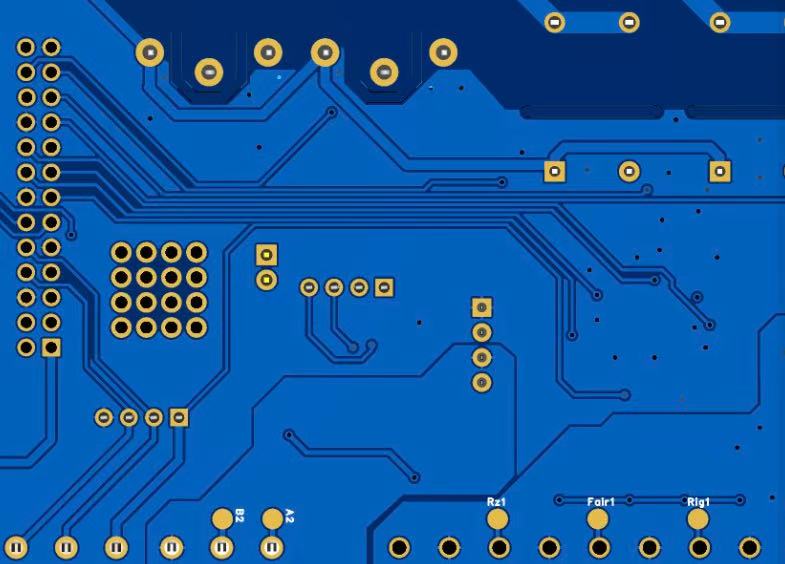
The concept of the Relationship Between Trace Width and Current refers to the direct connection between the physical width of a conductor trace on a PCB and the amount of current that the trace can safely carry without excessive temperature rise or performance degradation. When an electrical current passes through a copper conductor, the trace generates heat due to its electrical resistance. If the trace is too narrow for the required current, the resistance will be higher, causing more heat accumulation. Over time, this may lead to thermal stress, delamination, conductor damage, or even complete functional failure of the circuit.
At the core of the heat generation mechanism is Ohm’s Law and Joule heating:
Voltage Drop (V) = Current (I) × Resistance (R)
Heat Power Dissipated (P) = I² × R
Since narrower traces have higher resistance per unit length, they generate more heat for the same current. When heat cannot dissipate efficiently, the trace temperature rises, weakening the substrate and copper adhesion.
Two geometric factors govern a trace’s current-carrying ability:
| Parameter | Effect on Current Capacity |
|---|---|
| Trace Width | Wider traces reduce resistance and increase heat dissipation surface area |
| Copper Thickness | Thicker copper reduces resistance and increases conductor cross-sectional area |
For internal PCB layers, heat is trapped and cooling is limited, meaning internal traces require greater width for the same current compared to external traces.
Historically, engineers used IPC-2221 charts to estimate the minimum trace width required for a given current. However, modern testing and simulation data from IPC-2152 have improved accuracy by incorporating more variables such as:
Board material thermal conductivity
Environmental cooling conditions
Adjacent copper density
Dielectric layer thickness
Therefore, modern best practice requires basing design calculations on IPC-2152 whenever possible.

the Relationship Between Trace Width and Current
Thermal behavior is a central factor in understanding the Relationship Between Trace Width and Current, because heat is the direct byproduct of current flow through a conductor. Temperature rise is often the key limiting parameter that determines whether a trace can remain reliable during continuous operation.
Whenever electrical current passes through a copper trace, resistance converts some of the electrical energy into heat. The amount of heat generated is proportional to both the trace resistance and the square of the current. Copper is an excellent conductor, but its resistance, while low, is not zero. As current increases, the heating effect increases exponentially.
This means that doubling the current through a trace will not simply double the heat—it can increase heat by a factor of four. The design must therefore assume a margin that ensures the trace will not reach a temperature where material degradation begins.
Once heat is generated, it must dissipate into the surrounding environment. PCB traces dissipate heat through several mechanisms:
Conduction into adjacent copper areas
Conduction into the dielectric substrate
Convection at the PCB surface
Radiation (limited except at high temperatures)
Outer-layer traces dissipate heat more effectively because they are exposed to air and can rely on convection. Conversely, internal-layer traces are insulated and rely solely on conduction into the dielectric. This is why internal traces must typically be wider than external traces for the same current.
Copper density plays a significant role. When many traces or copper planes are present near a heat-generating trace, heat spreads more effectively. Conversely, isolated traces surrounded by resin heat more quickly. High copper fill ratios act as thermal spreaders. This phenomenon explains why the same trace width may perform differently depending on the surrounding layout.
Excessive temperature rise affects both the copper conductor and the substrate. Key failure risks include:
| Temperature State | Potential Effect |
|---|---|
| Moderate Increase | Elevated resistance and signal attenuation |
| High Increase | Mechanical fatigue, weakened copper-substrate adhesion |
| Severe Overheating | Trace delamination, conductor cracking, total circuit failure |
Many PCB base materials have a glass transition temperature (Tg). Repeated or prolonged operation close to Tg weakens the polymer matrix, accelerating aging and enabling copper peel or cracking. Hence, controlled heat rise is a long-term reliability consideration, not merely an electrical one.
Copper thickness is as important as trace width because both parameters jointly define the conductor cross-sectional area. A thicker copper layer allows more current to flow with lower resistance and less heat buildup.
PCB copper thickness is commonly specified in ounces per square foot (oz/ft²). Typical values include:
| Copper Weight | Approx. Thickness | Use Case |
|---|---|---|
| 0.5 oz | ~17 µm | Fine-pitch signal routing |
| 1 oz | ~35 µm | General-purpose circuitry |
| 2 oz | ~70 µm | High-current or power regulation paths |
| 3–6 oz | 105–210 µm | Heavy current industrial/power systems |
High-current applications such as motor drivers, battery management systems, and industrial power boards frequently use 2 oz copper or greater.
Copper plating processes add variability to final trace thickness. For example:
Finished copper may measure higher than base copper weight due to electrolytic plating.
Trace width may become narrower after etching depending on process precision.
Therefore, designs that operate close to thermal limits should assume worst-case thickness and tolerance.
Substrate choice determines how well heat spreads. FR-4, the most common PCB material, has thermal conductivity of approximately 0.3 to 0.4 W/m·K, which is relatively low. High-performance substrates such as ceramic-filled laminates or aluminum-backed PCBs provide significantly better thermal behavior.
Increasing trace width is the simplest modification, but it may not be feasible in dense routing areas. Increasing copper thickness is beneficial in power delivery regions but may complicate fine routing elsewhere.
In complex mixed-signal engineering, a hybrid approach—using thicker copper in selective layers or defining current-carrying regions as copper pours rather than narrow traces—often produces optimal results.
Effective PCB trace design requires both mathematical estimation and engineering judgment. Overreliance on blanket charts may lead to overly conservative or dangerously optimistic designs.
IPC-2152 provides empirical data from controlled thermal experiments and is widely regarded as the most reliable basis for determining safe current levels for given trace dimensions.
Compared to legacy IPC-2221 charts, IPC-2152 considers:
Internal vs external positioning
Copper plane proximity
Ambient cooling conditions
Thermal spreading through adjacent copper
Therefore, engineering teams are strongly advised to reference IPC-2152 whenever determining trace dimensions for sustained-current paths.
Modern PCB design workflows often integrate simulation software capable of modeling heat flow and current distribution. Common tool types include:
Field-solver trace resistance calculators
3D electro-thermal simulation suites
Embedded stack-up analyzers in ECAD systems
Simulation allows verification before prototyping, reducing risk and cost.
A typical recommended safety margin is 20–50% above the calculated minimum trace width, depending on:
Expected operating temperature variation
Intermittent vs continuous current duty
Environmental conditions such as enclosure airflow
Power electronics frequently employ even higher safety margins to ensure product durability.
When designing PCB traces to support specific current loads, reliability must remain the highest priority. While theoretical models and calculation tables provide guidance on minimum trace dimensions, real-world operating conditions often deviate from ideal assumptions. Therefore, practical safety margins are essential to ensure that the Relationship Between Trace Width and Current results in stable, long-lasting performance.
The copper trace does not fail instantly when overheated; rather, material degradation accumulates over time. Long-term exposure to elevated temperatures leads to:
Gradual rise in trace resistance
Decreased tensile strength and ductility of copper
Weakening of copper-to-substrate adhesion
Accelerated aging of dielectric materials
This means that designing traces simply to avoid immediate failure is insufficient. Instead, traces must be sized to prevent long-term thermal fatigue. For devices expected to operate for many years—such as automotive controllers, industrial power converters, or telecommunications infrastructure—this reliability factor becomes critical.
A commonly applied engineering practice is to apply a safety margin above the minimum required trace width. Typical guidelines include:
| Application Type | Minimum Safety Margin | Rationale |
|---|---|---|
| Consumer Electronics | 15–25% | Standard environmental conditions |
| Automotive / Transportation | 30–50% | High ambient heat and vibration |
| Industrial Power Systems | 50–100% | Continuous operation and harsh environments |
| Aerospace / Defense | Case-by-case, often >100% | Extreme reliability requirements |
Safety margins account not only for unexpected current spikes but also for manufacturing tolerances and long-term thermal drift.
Designers frequently face PCB layout environments where routing space is limited. In compact or high-density boards, increasing trace width may conflict with signal integrity routing, high-pin-count components, or microvia placement.
Possible approaches to managing these trade-offs include:
Placing power traces on outer layers for better cooling
Using copper pours instead of individual traces for current-carrying paths
Employing multi-layer power distribution structures
Integrating heat-spreading copper zones around current paths
In power delivery networks, it is common to route current along wide planes or polygon pours instead of treating them as discrete traces.
Not all circuits operate at constant current. Many systems—such as motor drivers, audio amplifiers, and DC/DC converters—experience periodic or transient current peaks. These peaks may be brief, but if they occur frequently, the accumulated heating effect may resemble continuous overload conditions.
Therefore, time-domain current behavior must be evaluated—not only the steady-state rating.
Understanding and effectively applying the Relationship Between Trace Width and Current is fundamental to reliable PCB design. The current-carrying ability of a trace is influenced not only by its geometric width but also by copper thickness, substrate material, thermal environment, and application conditions. Proper design must balance electrical performance, layout constraints, long-term material reliability, and manufacturing tolerances.
Through systematic trace dimensioning, careful attention to thermal behavior, and proactive collaboration with PCB manufacturers, designers can significantly reduce the risk of trace overheating and failure. Whether building consumer electronics, industrial power systems, automotive controls, or high-performance computing hardware, the principles outlined in this guide support safer, longer-lasting, and more efficient PCB designs.
1. What environmental factors should be considered when designing high-current traces?
Ambient temperature, enclosure airflow, humidity exposure, and installation location can all affect heat dissipation. Warmer or enclosed environments require wider traces or thicker copper.
2. Why do internal PCB traces require greater width than external traces?
Internal layers have limited heat dissipation ability because they are insulated by dielectric materials. Therefore, they need greater width to maintain acceptable temperature rise under load.
3. How does copper thickness affect current capacity?
Thicker copper increases cross-sectional area, lowering resistance and reducing heat buildup. This allows thinner or narrower traces to handle higher current safely.
4. Can multiple vias increase current capacity between layers?
Yes. Using multiple vias in parallel reduces bottleneck resistance and distributes heat more evenly, improving both performance and reliability.
5. Why should IPC-2152 be preferred over IPC-2221 for trace width calculations?
IPC-2152 is based on more comprehensive empirical thermal data and reflects real-world behavior more accurately, making it the recommended standard.
Connect to a Jerico Multilayer PCB engineer to support your project!
Request A Quote