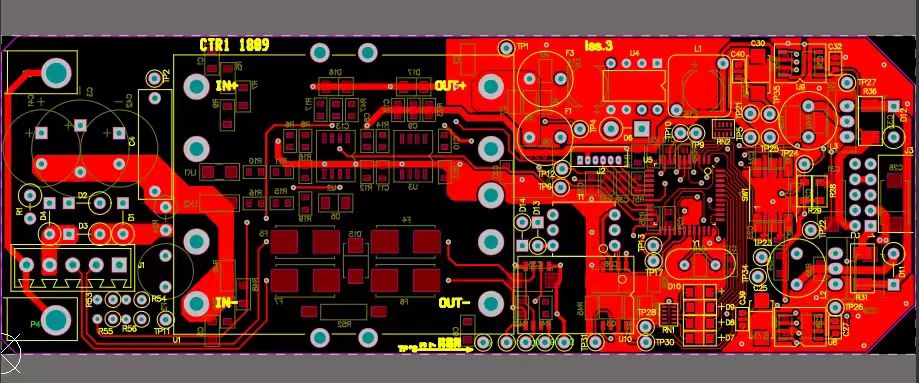
Printed circuit boards (PCBs) have evolved from simple copper traces on fiberglass to highly sophisticated signal-routing platforms enabling multi-gigabit data rates, precise timing, and ultra-low noise operation. At the heart of this transformation lies PCB Transmission Line engineering — the discipline of designing traces and layers to control impedance, minimize reflections, and preserve signal fidelity.
In high-speed digital and RF circuits, every millimeter of copper behaves like a transmission medium. Mismanaged impedance, discontinuities, or poor reference planes translate directly into data errors, electromagnetic interference, and shortened product lifespans. As clock frequencies exceed hundreds of megahertz and edge rates approach picoseconds, the margin for error becomes vanishingly small.
This article dives deep into PCB Transmission Line theory and practice, examining the benefits of well-engineered lines, the challenges posed by real-world manufacturing, and actionable strategies for taming signals at the board level.

PCB Transmission Line
A PCB Transmission Line is any conductor (or pair of conductors) on a PCB designed to carry high-speed signals where distributed effects such as inductance, capacitance, and wave propagation cannot be ignored. At low frequencies, a PCB trace behaves like a simple resistor; at high frequencies, it behaves as a distributed system described by transmission line equations.
Key parameters include:
Characteristic Impedance (Z₀): Determined by trace width, thickness, dielectric constant, and distance to reference plane.
Propagation Delay: How long a signal takes to travel per unit length.
Attenuation: Energy loss due to conductor resistance and dielectric loss.
Reflection Coefficient: Magnitude of signal reflected at discontinuities.
Understanding these factors allows engineers to match source, line, and load impedances, minimizing reflections and crosstalk.
Common geometries include:
Microstrip: A trace on an outer PCB layer with one reference plane beneath it.
Stripline: A trace buried between two reference planes, yielding tighter impedance control and lower EMI.
Coplanar Waveguide: A trace flanked by ground pours on the same layer, sometimes with via fences.
Each geometry offers different trade-offs in manufacturing complexity, space utilization, and performance.
The foremost benefit of a properly engineered PCB Transmission Line is maintaining signal integrity. Controlled impedance lines prevent data corruption, improve timing margins, and allow higher data rates. Designers can push interfaces like PCIe, USB, or high-speed DDR memory to their limits with confidence.
A well-implemented PCB Transmission Line also reduces electromagnetic interference. Consistent reference planes and smooth transitions reduce radiation, easing compliance with FCC, CE, or CISPR standards.
Though primarily about signals, proper PCB Transmission Line layout also assists with thermal distribution and even power integrity. Shorter return paths and minimized via stubs reduce localized heating and impedance peaks in the power delivery network.
Even with perfect CAD models, production realities — such as copper thickness tolerances, etching variation, and dielectric inconsistencies — can lead to mismatched impedances. High-speed designs must budget for these variances.
Parallel traces can couple capacitively and inductively. This crosstalk distorts waveforms and increases jitter. Designers combat this by maintaining adequate spacing, using differential pairs where possible, and employing guard traces or via fences.
Each via, pad, or connector introduces a discontinuity. Unmanaged, these can create impedance dips, reflections, and resonances. Techniques like back-drilling, stub removal, or using blind/buried vias help mitigate the effect.
Choosing the right dielectric material and layer stack is critical. High-frequency laminates such as Rogers or low-Dk FR-4 variants help maintain low loss, but increase cost. Designers must balance performance with manufacturability.
One of the most effective ways to ensure signal integrity is to optimize trace geometry. PCB Transmission Line performance depends on width, spacing, dielectric thickness, and copper thickness. Using impedance calculators or field-solvers allows designers to select optimal dimensions before fabrication.
For example:
Wider traces reduce resistance and skin-effect loss.
Consistent spacing between differential pairs maintains the differential impedance.
Smooth curves or 45° bends reduce signal reflection compared to sharp 90° turns.
Reference planes provide the return path for high-speed signals. A PCB Transmission Line with a solid, uninterrupted ground plane beneath it behaves predictably and minimizes loop area. Designers should avoid cutting reference planes with slots or gaps, especially under differential pairs.
Fabricators often provide coupons to test impedance. By measuring these coupons, engineers confirm that the PCB Transmission Line characteristics match specifications. This is another reason to coordinate early with a reliable manufacturer.
The dielectric constant (Dk) and dissipation factor (Df) of the PCB laminate directly affect signal speed and attenuation. High-speed designs may require advanced materials such as:
Rogers 4350B or 4003C for consistent Dk.
Isola FR408HR for improved performance over standard FR-4.
These materials allow tighter impedance control and lower loss for long PCB Transmission Line runs.
As explained in FAQ 1, rolled versus electrolytic copper foil can influence signal loss at high frequencies. Smoother foils yield less conductor loss and more stable impedance for PCB Transmission Line routing.
Thermal expansion, humidity, and flexural stress can alter dielectric properties over time. Designers must choose materials not only for electrical performance but also for reliability in harsh conditions.
As electronics systems continue to evolve, the importance of PCB Transmission Line design has never been more critical. High-speed digital interfaces, multi-gigabit networking, RF communications, and sensitive analog circuits all demand precise control over signal propagation, impedance, and noise. Neglecting these fundamentals can result in data corruption, electromagnetic interference, costly redesigns, and project delays.
A well-engineered PCB Transmission Line is more than just a conductor on a board; it is a carefully designed pathway that balances electrical, thermal, and mechanical constraints. Successful transmission line design integrates several key principles: material selection, trace geometry, reference plane continuity, via and connector management, and rigorous simulation and testing. Each decision, even a minor adjustment in trace width or dielectric thickness, can significantly affect signal integrity and overall system reliability.
Reflecting on decades of engineering practice, several lessons emerge:
Early Planning is Non-Negotiable – Signal integrity considerations must begin during the conceptual design phase. Designing first and considering transmission line requirements afterward invariably leads to compromises. Thoughtful stack-up planning, careful layer allocation, and impedance targets established upfront can prevent weeks or months of rework.
Collaboration with Fabricators is Critical – Partnering with experienced manufacturers, such as JM PCB, ensures that theoretical designs translate into practical, manufacturable boards. Fabricators bring knowledge about material behavior, tolerances, and advanced processes like back-drilling or blind/buried vias, which are often overlooked during design but crucial for high-performance boards.
Simulation and Testing Validate Real-World Performance – Even the most precise design can be affected by manufacturing variations. Tools like field solvers, time-domain reflectometry (TDR), and eye-diagram analysis bridge the gap between design intent and actual performance. Feedback from testing must inform iterative improvements, creating a continuous loop of quality enhancement.
Balancing Cost, Performance, and Time – Over-engineering adds unnecessary expense, while under-engineering compromises performance. The challenge lies in striking a balance between the ideal electrical characteristics and practical manufacturing constraints. Skilled engineers must weigh every decision against the impact on signal integrity, EMI, thermal performance, and production feasibility.
Emerging Trends Require Forward-Thinking Design – The future of PCB Transmission Line technology involves embedded traces, ultra-low-loss dielectrics, additive manufacturing, and AI-assisted routing. Designers must embrace these innovations to maintain competitiveness while understanding that new methods come with their own learning curves and trade-offs.
Education and Institutional Knowledge Matter – High-speed PCB design is a specialized skill. Organizations that invest in training, documentation, and knowledge transfer create resilient teams capable of handling increasingly complex designs. Lessons learned from previous projects, including both successes and failures, become invaluable references.
From my own perspective, the most successful projects are those that treat signal integrity not as a box to check but as a strategic enabler. Each PCB Transmission Line represents an opportunity to improve reliability, performance, and manufacturability. When approached systematically, with attention to material science, electromagnetic principles, and collaboration with experienced fabricators, even the most challenging high-speed designs can achieve predictable, repeatable results.
In conclusion, mastering PCB Transmission Line design is both a technical and strategic endeavor. It requires the intersection of physics, engineering judgment, simulation expertise, and practical manufacturing insight. Ultimately, the discipline of PCB Transmission Line design is about foresight, precision, and resilience. It is about understanding the physical realities of signals traveling at near-light speeds and crafting pathways that ensure those signals arrive intact. It is about turning theoretical knowledge into practical, manufacturable, and testable boards. Most importantly, it is about treating every trace as an integral part of the system, recognizing that in high-speed electronics, every millimeter counts.
The mastery of PCB Transmission Line design is not optional — it is essential. Those who invest in this expertise today will set the foundation for innovation, performance, and reliability for decades to come.
FAQ 1: What is the difference between rolled copper foil and electrolytic copper foil?
Rolled copper foil is produced by mechanically rolling copper into thin sheets, offering superior surface smoothness and mechanical strength. Electrolytic copper foil is deposited via an electrolytic process, making it more flexible and cost-effective but slightly rougher on a microscopic level.
FAQ 2: Why does impedance matching matter so much in a PCB Transmission Line?
Impedance mismatches cause reflections, which distort signals and reduce timing margins. Matching the source, line, and load ensures maximum power transfer and minimal distortion.
FAQ 3: How does dielectric constant variation affect PCB Transmission Line impedance?
A higher dielectric constant slows the signal and lowers impedance, while a lower dielectric constant speeds it up and raises impedance. Variations in dielectric constant between batches can shift impedance by several ohms.
FAQ 4: What is back-drilling in a PCB Transmission Line via?
Back-drilling removes unused portions of plated through-holes (stubs) after assembly. This reduces signal reflections and improves performance at high frequencies.
FAQ 5: How can I ensure my PCB Transmission Line design matches the manufacturer’s capabilities?
Work closely with your PCB vendor from the beginning. Share your stack-up, impedance requirements, and layer assignments. A qualified manufacturer, such as JM PCB, can run impedance modeling and suggest adjustments to ensure your design is feasible.
Connect to a Jerico Multilayer PCB engineer to support your project!
Request A Quote