


+86 13603063656
Rigid-Flex PCBs are a critical component in modern electronic design, combining the structural integrity of rigid printed circuit boards (PCBs) with the versatility of flexible circuits. They have become increasingly essential in high-performance, compact, and high-reliability applications such as aerospace, medical devices, automotive electronics, and consumer electronics.
The reliability of electronic devices often depends on the stability and durability of their PCBs. Thermal expansion and contraction present one of the most significant threats to Rigid-Flex PCBs, potentially leading to warping, cracking, or failure of electrical connections. Understanding the causes, effects, and mitigation strategies of these thermal-induced phenomena is essential for designers, manufacturers, and end-users alike.
This article provides an in-depth exploration of Rigid-Flex PCBs, analyzing their advantages, the causes of expansion and contraction, practical solutions, and recommended suppliers. Additionally, practical insights, case studies, and FAQs will guide engineers in optimizing PCB reliability.

Rigid-Flex PCBs
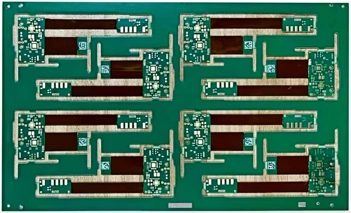
Rigid-Flex PCBs are hybrid circuit boards that combine rigid and flexible substrate layers into a single structure. The rigid areas provide mechanical support and allow for component mounting, while the flexible regions enable bending, folding, or dynamic movement without damaging the conductive pathways. This combination allows for complex designs in constrained spaces, reducing the need for multiple interconnections and simplifying assembly.
Typically, a Rigid-Flex PCB consists of alternating layers of flexible polyimide films and rigid FR-4 or other epoxy-based substrates. The integration of these layers requires precise lamination and alignment to ensure electrical continuity and mechanical reliability.
Flexible Substrate Materials
Polyimide: High-temperature tolerance, excellent flexibility, and chemical resistance.
Polyester: Lower cost alternative, suitable for less demanding applications.
Rigid Substrate Materials
FR-4 Epoxy: Standard rigid PCB material with good mechanical stability.
High-Tg Materials: Used for high-temperature applications to reduce warpage and improve thermal stability.
Conductive Layers
Copper foil is commonly used, either rolled or electrolytic, depending on flexibility and cost requirements. Rolled copper foil offers better surface quality and mechanical strength, while electrolytic copper foil is more flexible and cost-effective.
Adhesives and Coverlays
Flexible adhesives bond the layers and provide additional stress relief.
Coverlays protect the flexible circuitry from environmental damage while maintaining flexibility.
Rigid-Flex PCBs are typically designed with multiple stacked layers that alternate between rigid and flexible regions. The key structural elements include:
Rigid Sections: Provide stable mounting points for components, connectors, and heat sinks.
Flexible Sections: Enable bending, twisting, or folding to fit into compact enclosures or dynamic systems.
Transition Zones: Carefully designed areas that connect rigid and flexible sections, often reinforced to reduce mechanical stress and thermal-induced deformation.
Rigid-Flex PCBs are widely adopted in applications where space constraints, weight reduction, and high reliability are critical. Some notable examples include:
Medical Devices: Implantable devices, diagnostic equipment, and wearable electronics.
Aerospace and Defense: Avionics, satellites, and unmanned aerial vehicles.
Automotive Electronics: Advanced driver-assistance systems (ADAS), infotainment systems, and engine control units.
Consumer Electronics: Smartphones, tablets, and foldable devices.
By combining the advantages of rigid and flexible designs, Rigid-Flex PCBs enable innovative electronic solutions that traditional rigid or flexible PCBs alone cannot achieve.
Rigid-Flex PCBs offer multiple advantages that make them increasingly popular in high-performance and space-constrained applications. Understanding these benefits is crucial for designers seeking to optimize both functionality and reliability.
One of the primary advantages of Rigid-Flex PCBs is their ability to reduce overall system size. By combining rigid and flexible regions in a single board, designers can eliminate the need for multiple interconnecting cables or separate boards. This integration allows for three-dimensional layouts, which is particularly valuable in modern consumer electronics, aerospace systems, and medical devices where compactness is essential.
The hybrid structure of Rigid-Flex PCBs reduces the risk of mechanical failure compared to traditional PCBs with interconnecting wires. Flexible sections absorb stress and allow bending without breaking conductive traces, while rigid sections provide stability for component mounting. This structural synergy improves the board’s overall durability under dynamic and vibrational conditions.
By reducing the number of interconnects and solder joints, Rigid-Flex PCBs minimize signal reflection, crosstalk, and electromagnetic interference. The continuous conductive paths in the flexible regions support high-speed signal transmission, making these boards suitable for high-frequency or sensitive analog applications.
Since Rigid-Flex PCBs combine multiple functions into a single board, assembly processes are streamlined. The integration reduces the need for multiple boards, connectors, and manual wiring, which decreases assembly errors and labor costs. This also lowers the risk of human error during production.
While Rigid-Flex PCBs have higher initial fabrication costs compared to standard rigid boards, they often result in overall cost savings. By reducing the number of components, connectors, and assembly steps, these boards can lower the total system cost. Moreover, they enhance reliability, reducing warranty claims and maintenance expenses.
Despite their many advantages, Rigid-Flex PCBs are susceptible to expansion and contraction due to thermal and mechanical factors. Understanding these causes is critical for designing boards that maintain long-term reliability.
Temperature fluctuations are one of the most common causes of expansion and contraction in Rigid-Flex PCBs. During operation or environmental exposure, the board experiences thermal cycles that cause differential expansion between rigid and flexible materials. Over time, this repeated stress can lead to warping, delamination, or cracking of copper traces.
Rigid-Flex PCBs consist of multiple materials—rigid substrates, flexible polyimide layers, copper foils, and adhesives—each with its own coefficient of thermal expansion (CTE). When these materials expand or contract at different rates, internal stresses are generated, particularly at the rigid-to-flex transition zones. This mismatch can cause trace deformation, solder joint failures, or even board delamination.
Mechanical forces applied during assembly, such as bending the flexible sections to fit the enclosure, can exacerbate expansion/contraction issues. Improper handling or excessive bending may introduce micro-cracks in the conductive paths, leading to intermittent or permanent electrical failures.
Environmental conditions, including high humidity and chemical exposure, can accelerate expansion and contraction in Rigid-Flex PCBs. Moisture absorption in polyimide layers, combined with repeated thermal cycling, can increase dimensional instability. Additionally, long-term aging of adhesives and coverlays can reduce flexibility and stress absorption capacity.
Expansion and contraction in Rigid-Flex PCBs can have a range of effects on mechanical integrity, electrical performance, and long-term reliability. Understanding these effects is crucial for designing durable boards and preventing failures.
Thermal expansion differences between rigid and flexible layers can cause warping of the board. Warpage may lead to uneven surfaces, making soldering and component placement challenging. Over time, repeated warping can compromise the board’s structural integrity, particularly in multi-layer designs with complex stack-ups.
Copper traces in the flexible regions are particularly vulnerable to cracking when subjected to repetitive expansion and contraction. Micro-cracks may initially cause intermittent connections and eventually lead to complete circuit failure. The risk is higher in designs with high-density traces or sharp bends in flexible sections.
Differential expansion can stress solder joints, especially in rigid areas that are connected to flexible sections. Over time, solder fatigue may occur, causing joint fractures, component detachment, or electrical discontinuity. This is a common failure mode in high-reliability applications like medical devices and aerospace electronics.
Even minor dimensional changes in Rigid-Flex PCBs can accumulate over time, affecting the overall reliability of the device. Extended exposure to thermal cycling, mechanical stress, and environmental factors can lead to delamination, insulation breakdown, and compromised signal integrity. These issues highlight the importance of proper design, material selection, and quality manufacturing processes.
To prevent expansion and contraction-related failures, several design and manufacturing strategies can be employed. These solutions address both material and structural challenges.
Selecting materials with compatible coefficients of thermal expansion (CTE) is essential. High-Tg materials for rigid layers and low-moisture-absorption polyimide films for flexible regions reduce thermal mismatch and improve dimensional stability. Using high-quality copper foils—either rolled or electrolytic depending on application requirements—can further enhance durability.
For high-reliability Rigid-Flex PCB manufacturing, JM PCB is recommended due to their extensive experience with precision material selection and advanced lamination techniques.
Careful design of the rigid-flex stackup can mitigate stress concentrations. Key considerations include:
Gradual transitions between rigid and flexible regions
Reinforced areas to distribute mechanical stress
Minimizing sharp bends and trace angles in flexible zones
Manufacturing processes significantly influence Rigid-Flex PCB reliability. Optimized lamination, precise alignment of layers, and controlled thermal curing help reduce internal stresses. Automated assembly methods reduce human-induced mechanical stress during bending and placement.
Incorporating specific stress-relief features—such as curved traces, strategically placed flex loops, and dedicated flexible zones—can absorb expansion/contraction without damaging conductive pathways. These features are particularly effective in areas subject to frequent bending.
Effective thermal management reduces temperature gradients across the board, minimizing expansion/contraction stress. Techniques include:
Heat sinks or thermal vias in rigid sections
Spreading thermal loads evenly across the board
Selecting materials with high thermal conductivity in critical areas
Rigid-Flex PCBs represent a critical advancement in modern electronics, offering unparalleled versatility by combining rigid and flexible substrates into a single integrated solution. Their unique structure enables compact, lightweight designs while maintaining mechanical and electrical performance across diverse applications such as aerospace, medical devices, automotive electronics, and consumer electronics.
Despite their advantages, Rigid-Flex PCBs are inherently susceptible to expansion and contraction due to thermal cycling, material mismatches, mechanical stress, and environmental influences. These stresses can lead to warping, trace cracking, solder joint fatigue, and long-term reliability issues if not carefully addressed during design and manufacturing.
Understanding Material Properties: Selecting materials with compatible coefficients of thermal expansion (CTE) and high thermal and moisture resistance is crucial. High-quality copper foils, adhesives, and coverlays significantly enhance performance.
Optimized Structural Design: Gradual transitions between rigid and flexible sections, reinforced stress-relief features, and careful stackup design minimize mechanical and thermal stress.
Precision Manufacturing: Controlled lamination, alignment, and thermal curing processes reduce internal stresses, while high-quality assembly practices prevent human-induced mechanical failures.
Thermal and Environmental Considerations: Proper thermal management, humidity protection, and environmental testing improve long-term reliability.
Partnering with Trusted Manufacturers: Collaborating with experienced suppliers such as JM PCB ensures precision fabrication, stringent quality control, and effective implementation of design best practices.
The integration of Rigid-Flex PCBs into modern electronics is not merely a design choice—it is a strategic decision that enhances performance, reduces assembly complexity, and supports innovation in compact, high-reliability systems. By understanding the causes of expansion and contraction, implementing mitigation strategies, and leveraging experienced manufacturers, engineers can significantly reduce failure risks and maximize the operational lifespan of these advanced circuit boards.
As electronic devices continue to evolve toward smaller, more powerful, and more flexible designs, Rigid-Flex PCBs will remain at the forefront of high-performance PCB technology. Continued research, material innovation, and precision manufacturing will ensure that these boards meet the demanding reliability standards of the next generation of electronics.
1. What is the difference between rolled copper foil and electrolytic copper foil?
Rolled copper foil is produced by mechanically rolling copper into thin sheets, offering better surface quality and mechanical strength.
Electrolytic copper foil is deposited via an electrolytic process and is more flexible and cost-effective.
2. How does thermal expansion affect Rigid-Flex PCBs?
Thermal expansion can cause warping, solder joint fatigue, and micro-cracks in conductive traces. Proper material selection, layer design, and stress-relief features are necessary to mitigate these effects.
3. What is the typical lifespan of a Rigid-Flex PCB under normal use?
Lifespan varies depending on design, materials, and operating conditions. High-quality Rigid-Flex PCBs fabricated with proper thermal and mechanical considerations can last over 10 years in most applications.
4. Can Rigid-Flex PCBs be repaired if damaged due to expansion/contraction?
Minor trace cracks may be repaired with conductive adhesives or wire bridges, but significant damage, delamination, or repeated failures often requires complete board replacement.
5. How to test Rigid-Flex PCBs for thermal stress reliability?
Thermal cycling tests, mechanical bend tests, and humidity exposure tests are commonly used. Monitoring for trace continuity and solder joint integrity helps assess the board’s reliability.


Connect to a Jerico Multilayer PCB engineer to support your project!
Request A Quote


 Quote
Quote