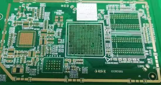
Signal Degradation refers to the gradual deterioration of an electrical signal as it travels along PCB traces, vias, and interconnects, resulting in:
Loss of amplitude
Increased noise
Phase distortion
Timing delays
Rise/fall time degradation
Crosstalk between adjacent conductors
A useful definition from a manufacturing perspective:
Signal Degradation is any unwanted alteration to an electrical waveform caused by PCB structural, material, or process-related factors.
This degradation becomes especially critical in applications involving:
High-speed digital signals
RF and microwave systems
High-density multilayer boards
Automotive radar and ADAS
Servers and networking hardware
As clock speeds rise, even microscopic imperfections create significant electrical inconsistencies.

Signal degradation
Signal Degradation arises from multiple interacting mechanisms:
Resistive losses increase with frequency due to the skin effect. Rough copper traces intensify this loss.
Energy dissipates inside the substrate material. Dielectric constant (Dk) and dissipation factor (Df) both contribute.
Any transition—trace width changes, via stubs, connectors—reflects part of the signal.
Electromagnetic coupling between traces increases as spacing decreases.
Fluctuating reference planes distort signal return paths.
These mechanisms combine, creating cumulative degradation that grows with distance, frequency, and manufacturing precision.
Manufacturing greatly influences the severity of Signal Degradation. The most common contributors include:
Rough copper foils increase conductor loss and degrade high-speed signals. Rolled copper can significantly improve smoothness.
Poor lamination control leads to impedance shifts.
Non-uniform dielectric regions distort propagation characteristics.
Stubs introduce unwanted resonances, especially above 5–10 GHz.
Return path discontinuities cause reflection and added loop inductance.
Over-etching, under-etching, or etch-back creates inconsistent widths.
Modern high-speed boards rely on substrates such as:
PTFE composites
Hydrocarbon ceramic laminates
Ultra-low Df resins
High-performance FR-4 variants
Low dielectric loss directly reduces energy dissipation.
Manufacturers use:
Tight trace width tolerances
Precise dielectric thickness lamination
Automated optical inspection
Cross-sectional analysis
These practices ensure that propagation characteristics remain stable.
Manufacturers use:
Rolled annealed copper
Reverse treated copper
Ultra-low-profile copper (ULP)
Smooth surfaces reduce high-frequency conductor loss.
Back-drilling eliminates unused barrel sections, preventing resonant reflections.
This involves:
Fine-line etching chemistry
Differential etch control
Plasma treatment
Clean edges reduce unpredictable impedance variance.
Manufacturing enables performance, but layout determines the resulting electrical environment. Among the most effective strategies:
Keep reference planes continuous.
Crosstalk scales with trace proximity.
Each via transition introduces delay and reflection.
Length matching and controlled impedance keep signals synchronized.
Low Df materials significantly reduce dielectric loss.
Spread-glass fabrics reduce glass-weave skew.
At high speeds, copper profile matters more than thickness.
Cost-driven boards may mix standard FR-4 with high-speed materials.
Manufacturers rely on:
Measures impedance uniformity.
Extracts insertion and return loss.
Validates coupling effects.
Reveals real-world signal openness and jitter.
Df determines how much energy is absorbed by the dielectric. Materials with high Df degrade signals faster over distance.
| Material Type | Typical Df Range | Application |
|---|---|---|
| Standard FR-4 | 0.015–0.020 | Low-speed designs |
| Mid-loss FR-4 | 0.009–0.012 | USB 3.0, HDMI |
| Low-loss Materials | 0.002–0.006 | 10–28 Gbps |
| Ultra-low-loss Materials | 0.0008–0.002 | mmWave, RF, 56–112 Gbps |
Eye diagrams remain one of the most intuitive and insightful measurement tools for high-speed digital systems. They combine hundreds or thousands of waveforms to form a statistical picture of performance.
A clean eye indicates stable, well-preserved signals. A closed or distorted eye points directly to Signal Degradation.
Eye height → affected by amplitude loss
Eye width → affected by jitter
Crossing point → impacted by skew
Rise/fall times → influenced by dielectric/conductor losses
Noise margins → degraded by crosstalk or power integrity noise
Engineers often evaluate these measurements alongside bit error rate (BER) testing to determine whether a PCB meets high-speed channel requirements.
While TDR and VNA reveal physical and electrical characteristics, BER testing measures real-world data transmission reliability.
A BER tester sends streams of pseudo-random binary sequences (PRBS) across a channel and counts errors.
Accumulated degradation effects
Random jitter vs. deterministic jitter
Whether a channel meets required performance metrics
The practical impact of material and manufacturing quality
In systems like PCIe, USB4, or 100G Ethernet, BER requirements are incredibly strict (e.g., 10⁻¹² or 10⁻¹⁵), meaning even tiny Signal Degradation effects can push a system out of compliance.
Electrical testing must be paired with physical inspection to fully understand degradation sources.
Used to evaluate:
microvia alignment
plating voids
via quality
buried structures
internal layer alignment
Poor via construction is a major contributor to reflection-induced Signal Degradation.
AOI focuses on:
line width accuracy
etch variations
copper surface condition
pattern defects
Even small edge irregularities can alter impedance.
Microsections validate:
dielectric thickness accuracy
copper roughness
resin distribution
glass weave alignment
shape of etched traces
Microsectioning provides the final confirmation of whether manufacturing precision meets the expectations needed to minimize Signal Degradation.
Managing lamination conditions is essential to preventing Signal Degradation because material uniformity directly determines dielectric stability, copper adhesion, and impedance consistency. Lamination is often considered a mechanical process, but in reality, every temperature ramp rate and pressure cycle influences the electromagnetic environment that signals must navigate.
During multilayer PCB fabrication, prepreg resin flow must properly encapsulate conductors without creating voids or resin-starved regions. These microscopic defects do more than compromise mechanical strength—they produce unpredictable impedance pockets and localized attenuation hotspots. When signals encounter these non-uniformities, transitions become distorted, edge rates decline, and timing uncertainty increases.
Lamination technicians must therefore balance multiple variables: resin viscosity, foil roughness, glass transition temperature, dehydration procedures, and press dwell time at key stages. My experience suggests that manufacturers who overly prioritize throughput tend to overlook subtle lamination deviations that accumulate over repeated product runs. In contrast, high-end fabricators employ closed-loop lamination systems capable of automatically syncing pressure and heat distribution, ensuring each substrate experiences identical curing profiles.
When lamination is conducted with precision, PCBs maintain consistent dielectric thickness and stable trace geometries, both critical for high-frequency and high-speed systems. When it is not, Signal Degradation emerges in the form of attenuation, reflections, and crosstalk—all of which could have been prevented through disciplined process control.
Preserving signal integrity is not a single task, nor is it merely a design concern—it is a full-spectrum manufacturing philosophy. Throughout this article, the various dimensions of controlling electrical behavior inside a PCB have been examined, ranging from copper roughness and dielectric stability to plating uniformity, microvia structure, contamination control, and disciplined lamination processes. Each manufacturing step contributes to the electrical clarity of a PCB’s signal path, and each presents its own opportunities for either preserving or damaging high-speed performance.
From a broader perspective, solving issues related to waveform clarity and transmission stability requires a shift toward viewing fabrication as an integrated electromechanical system rather than a set of isolated steps. Signal quality emerges not simply from how a trace is routed, but from whether the underlying materials, surface finishes, via structures, and lamination profiles are engineered to behave consistently at the microscopic scale. This necessity becomes even more pressing as products trend toward multi-gigabit data rates, extreme miniaturization, and highly sensitive RF performance requirements.
In my own professional view, advanced PCB manufacturing is entering an era where passive control is no longer sufficient. Manufacturers must adopt proactive signal-preservation practices—predictive modeling of copper grain behavior, real-time chemical monitoring in plating, adaptive laser drilling, and empirical dielectric characterization. The goal is no longer to meet minimum specifications but to eliminate variability before it manifests as performance loss in the field.
Another key trend is the increasing reliance on manufacturing partners who not only understand electrical performance but can reliably reproduce it at scale. This is where fabricators such as JM PCB demonstrate a meaningful advantage. By integrating materials science expertise with automated process control, they help ensure that the final PCB does not merely function, but performs with predictable signal behavior across environmental, frequency, and lifetime conditions.
Ultimately, combating waveform deterioration is not simply a matter of repairing isolated issues—it is about engineering a complete fabrication environment where the electrical path is protected from the moment copper meets laminate. When manufacturing discipline, precise material control, and process transparency converge, modern electronics gain the foundation they need to operate with clarity, speed, and long-term reliability.
In this sense, the pursuit of better signal performance is not just a technical challenge but a reflection of evolving industry values: precision, predictability, and long-term engineering responsibility. As high-performance electronics continue to push boundaries, the manufacturers who embrace these principles will be the ones that define the next generation of reliable, high-speed PCB technology.
Rolled copper foil is mechanically rolled into thin sheets, resulting in excellent surface smoothness and higher durability. Electrolytic copper foil is deposited using an electrochemical process and is more cost-effective and flexible, though typically rougher.
Yes. Copper roughness increases conductor losses and causes higher attenuation, especially in high-speed or RF applications.
Materials with lower and more stable dissipation factors (Df) and dielectric constants (Dk) reduce attenuation, phase distortion, and impedance variability.
Absolutely. Microvoids, rough walls, or inconsistent plating thickness increase resistive losses and disrupt signal flow.
Uneven lamination creates dielectric thickness variation, which disrupts impedance and leads directly to waveform distortion.
Connect to a Jerico Multilayer PCB engineer to support your project!
Request A Quote