Engineered for Reliability: PCB Slip Rings for Demanding Rotary Applications
Introduction: Why PCB Slip-Rings Redefine Rotary Applications
In today’s world of precision engineering and continuous rotation mechanisms, electrical connections must be as reliable as the mechanical design that supports them. Traditional slip rings—while effective—often face challenges with size, wear, and signal integrity. This is where PCB Slip Rings emerge as an advanced solution.
Unlike conventional brush-based slip rings, PCB Slip Rings use printed circuit board technology to create compact, precise, and durable rotary connections. They offer consistent transmission of power and signals in applications where space is limited and reliability is paramount.
From medical imaging devices like CT scanners, to aerospace gyroscopes and industrial robots, these slip rings provide engineers with a compact yet robust means of ensuring continuous 360° rotation without compromising electrical performance.
As the global demand for high-density signal transmission and miniaturized components continues to grow, the role of PCB Slip Rings will only expand, making them the backbone of next-generation rotary systems.
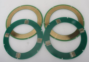
PCB Slip Rings
Understanding PCB Slip-Rings – A Detailed Technical Overview
At their core, PCB Slip Rings are electromechanical devices designed to allow the transmission of power, data, or mixed signals from a stationary part of a system to a rotating part.
Structural Foundation of PCB Slip Rings
Unlike traditional slip rings that rely on bulk copper rings and graphite brushes, PCB Slip-Rings use printed circuit boards as conductive layers. This design:
The contact is typically established by gold-to-gold or gold-to-graphite interfaces, ensuring low friction and minimal electrical noise.
Electrical Transmission Capabilities
PCB Slip Rings excel in transmitting:
-
Low-voltage control signals.
-
High-frequency data transmission such as Ethernet, USB, or HDMI.
-
Mixed signals, making them versatile for multi-functional rotary systems.
Mechanical Integration
PCB Slip Rings are commonly integrated into:
This versatility allows engineers to minimize space requirements while maximizing performance.
Engineered for Reliability: PCB Slip-Rings for Demanding Rotary Applications
Advantages of PCB Slip Rings in High-Reliability Systems
Designers gravitate to this architecture for three reasons: signal integrity, mechanical longevity, and system compactness. Together, they reduce field failures and lower total cost of ownership in continuous-rotation subsystems.
Compact signal density without crosstalk
Using multilayer build-ups with controlled impedance traces, these devices route dozens to hundreds of channels in a small form factor. Guard traces and well-placed reference planes corral return currents and tame coupling, enabling mixed power-and-data in one rotary interface.
Low and stable contact resistance
Gold-on-gold contacts, micro-profiled tracks, and compliant brush geometry yield a narrow band of contact resistance over life. The result: cleaner logic thresholds, less common-mode wander, and fewer retries for fast serial links.
Predictable wear and long service life
Because the conductive paths are photolithographically defined rather than machined, contact tracks are geometrically consistent. Combined with optimized contact force and low-shear lubricants, wear debris is minimized, extending maintenance intervals.
EMC performance by design
Layer stacks, via stitching, and 360° ground shields create short, repeatable return paths. That means better emissions margins and higher immunity in noisy environments such as inverter-driven motors or radar pedestals.
Thermal peace of mind
Copper pours and thermal vias spread joule heating, while contact pairs run cooler thanks to reduced friction. Lower operating temperature slows lubricant degradation and preserves spring temper.
PCB-Slip Rings: Advantages and Reliability of PCB-Slip Rings
Advantages of PCB Slip Rings
-
Tight stack-up tolerances: Fine control of dielectric thickness and copper roughness improves high-speed channel matching and reduces skew.
-
Surface finish integrity: ENIG or hard gold over nickel keeps contact resistance low and stable, especially under humidity/thermal cycling.
-
Cleanroom track processing: Reduces particulate inclusion in contact paths, lowering early-life noise bursts.
-
Parametric serialization: Per-unit traceability and process logs simplify root-cause analysis and PPAP documentation for regulated industries.
-
Application-specific modules: Options for mixed-signal (power + RF + high-speed data), fiber-optic rotary joints (FORJ) co-axiality, and integrated fluid rotary unions.
Reliability Characteristics of PCB Slip Rings
-
Life testing to mission profiles: Duty-cycle, RPM, and load current can be profiled to your use case; data typically shows flat resistance drift through most of life, with a gentle rise near wear-out.
-
Environmental endurance: Designs are validated for salt fog, dust, shock, and vibration; seals and venting prevent pressure differentials from pulling contaminants across contacts.
-
Contact metallurgy stability: Hard gold thickness and under-plating choices resist pore corrosion and fretting, stabilizing micro-ohm-scale variations that would upset sensitive ADCs and PLLs.
-
Serviceability: Modular rings and brush blocks enable quick swap during scheduled maintenance without disturbing the rotary bearing set.
PCB Slip Rings in Medical Equipment Applications
CT gantries, angiography C-arms, and surgical robots need 24/7 uptime and immaculate signal paths.
-
Low acoustic noise: Optimized contact force profiles and low-shear lubricants prevent micro-chatter that could propagate into imaging pipelines.
-
Ultra-clean materials: Low outgassing laminates and biocompatible surface finishes help maintain clinical cleanliness standards.
-
Hot-swap designs: Drawer-style brush modules shorten downtime during preventive maintenance windows.
PCB Slip Rings in Industrial Automation and Robotics
Cobots, rotary indexers, tool changers, and AGVs push for compactness and quick field service.
-
High-cycle durability: Brush metallurgy and spring temper are selected to survive millions of revolutions across wide temperature bands.
-
Noise immunity near drives: Segregated ground planes and star-point returns keep VFD hash out of encoder and fieldbus channels.
-
Modular upfit: Add-a-deck architecture lets integrators scale from a 12-channel control ring to a 96-channel mixed-signal assembly as I/O needs grow.
PCB Slip Rings in Renewable Energy Systems
Yaw systems in wind turbines and heliostat drives face moisture, temperature swing, and lightning environments.
-
Moisture defenses: Labyrinth seals and desiccants combat condensation produced by day-night cycles.
-
Transient robustness: Surge suppression and ring segmentation help ride through grid faults and switching events.
-
Service intervals aligned to tower climbs: Predictable wear models allow alignment with gearbox and blade inspections.
Engineering Reliability: How PCB Slip Rings Withstand Harsh Environments
Reliability isn’t an accident; it’s an accumulation of small, disciplined choices.
Materials and finishes
-
Contact surface: Hard gold maintains low friction and resists corrosion; nickel under-layers block copper diffusion.
-
Laminate selection: Tg, Td, and CTE compatibility with the mechanical hub prevent warpage and solder joint fatigue.
-
Lubrication: Vacuum-compatible or food-grade variants are available when process constraints dictate.
Mechanical architecture
-
Brush geometry: Multi-finger or bifurcated bundles increase contact redundancy and average out micro-discontinuities.
-
Track profiling: Micro-textures retain lubricant films and disperse debris away from the active contact line.
-
Bearing isolation: Electrically isolating the bearing race prevents stray currents from pitting rolling elements.
Electrical architecture
-
Segregated planes and stitching: Create quiet zones for ADCs and high-speed links.
-
Current-sharing for power: Parallel tracks and heavy copper spreads lower I²R heating and increases fault tolerance.
-
Health telemetry: Embedded sense lines monitor contact resistance and temperature for predictive maintenance.
Design Innovations in PCB Slip Rings for Compact Rotary Systems
-
Hybrid rotary unions: Co-axial integration with FORJ or fluid channels reduces stack length and leak paths.
-
Folded-flex interposers: Flex tails route vertically to save axial height without risking via-in-pad voiding.
-
Additive manufacturing for carriers: Printed titanium or polymer carriers reduce weight while maintaining stiffness.
-
Smart diagnostics: On-board microcontrollers can timestamp micro-glitches and correlate with speed or load to forecast service.
Manufacturing Process of PCB Slip Rings: Precision and Quality Control
A robust process underwrites field reliability.
-
DFM and stack-up lock-down: Impedance, copper balance, and resin content are frozen early to prevent late surprises.
-
Photolithography and etch: Tight track edge definition reduces impedance ripple and contact roughness.
-
Plating: Controlled nickel/gold thickness ensures both wear life and stable resistance.
-
Lamination: Press cycles tuned to minimize voids and resin-starvation at the track shoulders.
-
CNC routing and balancing: Concentricity and mass balance reduce wobble and contact chatter at speed.
-
Assembly: Brush blocks installed with measured preload; torque and runout captured in travelers.
-
End-of-line test: Contact resistance, noise, hipot, and functional data link checks validate performance before ship.
Reliability Testing of PCB Slip Rings for Mission-Critical Uses
-
Life cycling: Real-world duty cycles at temperature to capture wear-out behavior.
-
Shock & vibe: Sine/random spectra to validate spring retention and track adhesion.
-
Thermal-humidity bias (THB): Confirms corrosion resistance and pore-free finishes.
-
Ingress protection verification: Water/dust exposure according to the target IP rating.
-
Data-link margining: Eye diagrams and BER across speed and temperature extremes.
FAQ on PCB Slip Rings and Related Materials
-
What is the difference between rolled copper foil and electrolytic copper foil?
Rolled copper foil is produced by mechanically rolling copper into thin sheets, offering better surface quality and mechanical strength. Electrolytic copper foil is deposited via an electrolytic process and is more flexible and cost-effective.
-
How do these rotary interfaces handle high-speed data without errors?
Through controlled-impedance traces, short return paths, guarded routing, and gold contacts with stable resistance. Channel simulations and BER testing confirm margin across temperature, speed, and life.
-
What IP rating should I target for dusty or humid plants?
For indoor dust exposure, IP5X is often sufficient; add the second digit (e.g., IP54/IP55) based on expected washdown or condensation. Critical outdoor applications may justify IP65+ with breathers to avoid pressure-driven ingress.
-
When should I choose hard gold over ENIG on contact tracks?
Hard gold excels for sliding wear and long life; ENIG is excellent for solderability and moderate wiping. For primary contact paths under continuous rotation, hard gold with a suitable under-plate is typically preferred.
-
How can I reduce electrical noise in encoder and sensor signals?
Isolate grounds, use twisted pairs with matched impedance, route away from motor phases, and specify brush preload that avoids micro-bounce. Adding sense lines for health monitoring can flag rising resistance before it becomes noise.
our Jerico Multilayer PCB Factory pcbsupplier.com


 Quote
Quote