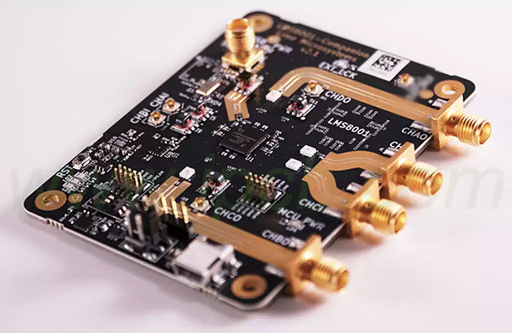
High-Density Interconnect (HDI) technology has become an indispensable part of modern electronic design, particularly when high-speed signal integrity is crucial. Rogers HDI Boards are a specialized subset of HDI boards, distinguished by their superior dielectric materials, low loss characteristics, and consistent thermal performance. These features allow engineers to achieve higher routing density, reduce signal distortion, and maintain reliable operation in high-frequency applications.
Unlike standard FR-4 substrates, which often suffer from higher dielectric losses and limited thermal stability, Rogers HDI Boards are engineered to support frequencies well into the gigahertz range. This makes them particularly suitable for RF modules, 5G devices, high-speed computing, and aerospace electronics. The boards combine precision laminates with advanced fabrication techniques, ensuring that signal integrity is maintained even in complex multi-layer designs.
Reflecting on their impact, I find that Rogers HDI Boards not only push the technical limits of PCB design but also demand a more strategic approach to layout, stack-up planning, and thermal management. Engineers must understand the interplay of dielectric properties, copper foil characteristics, and via design to fully exploit the potential of these boards.

Rogers HDI Boards
The exceptional performance of Rogers HDI Boards begins with their material composition. These boards typically utilize high-performance laminates such as RO4350B, RO4003C, or RT/duroid series, which offer low dielectric loss (tan δ), tight dielectric constant (Dk) tolerances, and excellent thermal conductivity.
Dielectric Layer:
The dielectric material directly affects signal speed, attenuation, and impedance consistency. Rogers laminates provide a low-loss environment, crucial for high-frequency applications where even minor losses can lead to significant signal degradation.
Copper Foil:
The copper foil used in these boards can be either rolled copper or electrolytic copper, each with unique characteristics. Rolled copper offers superior surface uniformity and mechanical strength, which is beneficial for high-speed signal routing and via reliability. Electrolytic copper, on the other hand, is more flexible and cost-effective, often used in applications where slight compromise on surface roughness is acceptable.
Prepreg and Adhesives:
Advanced prepreg materials with controlled resin content ensure consistent dielectric properties between layers. This uniformity is vital for maintaining impedance control across multiple signal layers.
Via Structures:
Microvias, blind vias, and buried vias are strategically employed to achieve high routing density while maintaining electrical performance. The via diameter, aspect ratio, and plating method significantly influence high-frequency signal integrity.
From my experience, attention to these material details often determines whether a high-speed design will perform as expected or suffer from unexpected reflections, crosstalk, or insertion loss.
The primary advantage of Rogers HDI Boards lies in their ability to preserve high-speed signal integrity. Key electrical characteristics include:
Low Dielectric Loss: Rogers laminates exhibit minimal signal attenuation even at frequencies above 10 GHz. This allows for longer trace lengths without significant degradation.
Tight Dk Tolerance: Consistent dielectric constant ensures predictable impedance control, which is critical for differential pairs and matched-length routing.
Reduced Crosstalk: Advanced via structures and careful layer stack-up help mitigate interference between adjacent signals.
Thermal Stability: The combination of high Tg materials and low CTE mismatch reduces warpage and maintains consistent electrical performance under temperature cycling.
When designing high-speed circuits, I have found that the choice of Rogers HDI Boards can often simplify signal integrity challenges that would otherwise require extensive simulation and compensation. Moreover, integrating these boards with precision routing and proper termination strategies ensures minimal reflection and signal loss across high-frequency channels.
Rogers HDI Boards offer a range of advantages over conventional PCB materials, particularly in applications demanding high-frequency performance and compact designs:
High-Speed Signal Performance
With low dielectric loss and stable dielectric constant, Rogers HDI Boards maintain signal integrity even at multi-gigahertz frequencies. This minimizes insertion loss, signal reflection, and jitter, crucial for RF, 5G, and high-speed computing applications.
Enhanced Routing Density
Microvias and blind/buried via structures enable higher layer counts without increasing board size. This facilitates compact designs in smartphones, wearables, and aerospace electronics where space is at a premium.
Thermal and Mechanical Stability
High Tg laminates reduce warpage under thermal cycling, while low CTE ensures minimal mismatch with copper layers. These properties are critical for multi-layer boards with dense component placement.
Reliable Manufacturing
Rogers laminates are less sensitive to moisture absorption and maintain dimensional stability during reflow soldering. This reduces defects and enhances yield in mass production.
Versatility Across Applications
From radar and satellite systems to advanced consumer electronics, these boards allow engineers to implement complex high-speed designs without compromising reliability.
Reflective Insight: In my experience, the adoption of Rogers HDI Boards shifts the design focus from compensating for material limitations to optimizing layout, signal routing, and thermal performance. Engineers can focus on innovation rather than mitigation of substrate issues.
Designing with Rogers HDI Boards requires a meticulous approach to stack-up, trace routing, and signal integrity analysis:
Layer Stack-Up Optimization
High-speed signals are best routed in controlled impedance layers with reference planes placed above and below. Microvias allow vertical routing without sacrificing signal quality.
Impedance Control
Maintaining consistent differential pair spacing and trace width ensures minimal reflection. Rogers laminates provide tight dielectric tolerance, simplifying impedance calculations.
Crosstalk Mitigation
Signal spacing, ground plane placement, and via shielding are key strategies. Rogers HDI Boards, combined with optimized layout, reduce crosstalk even in dense routing scenarios.
Power Integrity
Proper placement of power and ground planes minimizes voltage droop and noise coupling. Designers often implement decoupling capacitors and bulk power planes to maintain stable voltage across the board.
Simulation-Driven Design
Utilizing electromagnetic simulation tools allows accurate prediction of signal behavior, including insertion loss, return loss, and eye diagram analysis.
Reflective Insight: High-speed design with Rogers HDI Boards often shifts the engineering challenge from material limitations to precise planning and verification. Advanced EDA tools and careful attention to microvia placement can significantly improve performance and reduce iteration cycles.
Thermal performance is a critical factor for high-frequency circuits:
Material Thermal Properties
Rogers laminates exhibit high Tg and low CTE, maintaining structural integrity under repeated thermal cycling. This prevents warpage and delamination.
Copper Weight and Plane Distribution
Heavy copper layers and optimized plane distribution enhance heat dissipation. Designers can integrate thermal vias to transfer heat from high-power components to larger planes.
Component Placement
Positioning heat-generating components strategically prevents localized hot spots. Coupled with Rogers HDI Boards’ thermal stability, this ensures consistent electrical performance.
Thermal Simulation
Thermal analysis tools can predict heat distribution, allowing designers to preemptively address potential failure points.
Reflective Insight: Effective thermal management is not just about material choice; it’s a holistic process involving board layout, component selection, and active/passive cooling strategies. Rogers HDI Boards provide a stable foundation to implement these strategies without introducing signal integrity issues.
Manufacturing Rogers HDI Boards requires precision and attention to detail:
Lamination and Layer Bonding
Controlled pressure and temperature ensure consistent bonding of multiple layers without voids. High Tg laminates tolerate aggressive lamination cycles without degradation.
Microvia Formation
Laser drilling allows precise formation of microvias with minimal damage to surrounding material. Plating techniques ensure reliable via conductivity and adhesion.
Surface Finishing
Advanced finishes such as ENIG or immersion silver enhance solderability without compromising high-frequency performance.
Quality Control
Automated optical inspection (AOI), X-ray imaging, and impedance testing are essential to maintain consistency. Rogers HDI Boards require more rigorous QC due to tight tolerances and high-speed design demands.
The versatility of Rogers HDI Boards allows them to meet the demanding requirements of a wide range of industries:
Telecommunications and 5G Systems
High-frequency performance and low-loss characteristics make Rogers HDI Boards ideal for 5G base stations, antenna modules, and RF front-end circuits. The tight Dk tolerance ensures signal integrity across multiple gigahertz channels, critical for high-speed data transmission.
Aerospace and Defense
In aerospace applications, reliability and thermal stability are paramount. Rogers HDI Boards enable compact, lightweight designs for radar, satellite communication, and avionics systems, where even minor signal degradation can have critical consequences.
High-Performance Computing
Servers, GPU accelerators, and data centers require dense multi-layer boards to support fast memory and processor interconnections. Rogers HDI Boards facilitate high-density routing and microvia integration without compromising signal fidelity.
Consumer Electronics
Smartphones, tablets, and wearable devices benefit from the miniaturization enabled by HDI technology. Rogers HDI Boards allow more components in less space while maintaining high-speed data paths for multimedia processing and wireless communication.
Automotive Electronics
Advanced driver-assistance systems (ADAS), infotainment, and electric vehicle power modules demand reliable high-speed PCBs. Rogers HDI Boards combine thermal resilience with signal integrity to ensure stable performance under harsh operating conditions.
Reflective Insight: The widespread adoption of Rogers HDI Boards reflects a paradigm shift in PCB design—from accommodating physical limitations to leveraging advanced materials for higher performance and more compact, efficient layouts.
Ensuring the reliability of Rogers HDI Boards requires rigorous testing and validation:
Electrical Testing
Impedance Verification: Ensures controlled impedance and consistent signal transmission.
High-Frequency Loss Measurement: Confirms low insertion loss across GHz-range signals.
Crosstalk Evaluation: Detects undesired coupling between adjacent traces.
Thermal and Mechanical Testing
Thermal Cycling: Simulates real-world operating conditions to detect potential delamination or warpage.
Mechanical Stress Testing: Verifies via and board integrity under bending or vibration.
Environmental Testing
Rogers HDI Boards must maintain performance under humidity, temperature fluctuations, and chemical exposure. Boards are typically subjected to accelerated aging tests to predict long-term reliability.
Failure Analysis and Corrective Measures
In the rare event of failure, X-ray inspection, cross-sectioning, and signal integrity re-testing allow engineers to pinpoint the root cause. This information feeds back into improved design and manufacturing protocols.
Reflective Insight: In high-speed applications, the cost of failure is high. Testing protocols for Rogers HDI Boards go beyond standard FR-4 processes, emphasizing predictive analysis and comprehensive validation. This proactive approach ensures long-term reliability for mission-critical electronics.
Rogers HDI Boards represent a transformative technology for high-speed, high-density PCB applications. Their combination of low-loss laminates, precise copper foil options, thermal stability, and advanced via structures enables engineers to achieve exceptional signal integrity in challenging environments.
Reflecting on the broader implications, Rogers HDI Boards not only address current high-speed design challenges but also pave the way for future innovations in telecommunications, aerospace, consumer electronics, and automotive industries. By mastering these boards, engineers can unlock new possibilities in miniaturization, performance, and reliability, setting a new benchmark for advanced electronic design.
Answer: Rolled copper foil is produced by mechanically rolling copper into thin sheets, offering better surface quality and mechanical strength. Electrolytic copper foil is deposited via an electrolytic process and is more flexible and cost-effective. Choice depends on the application’s mechanical and high-frequency performance requirements.
Rogers HDI Boards offer lower dielectric loss, tighter Dk tolerance, better thermal stability, and support for higher-frequency operation. FR-4 boards are cost-effective for lower-speed applications but may suffer signal integrity issues at multi-gigahertz frequencies.
Yes. Their low-loss laminates, precise impedance control, and high-density via structures make them ideal for 5G front-end modules, antennas, and base station electronics.
High-performance boards can range from 6 layers up to 16 or more, depending on routing complexity and high-frequency signal requirements. Microvias and blind/buried via technology facilitate dense multi-layer designs without significantly increasing board thickness.
While Rogers HDI Boards are more expensive than standard FR-4, the benefits in signal integrity, reliability, and reduced design iteration can offset initial costs. Working with experienced manufacturers like JM PCB can optimize material selection and fabrication processes, improving ROI and reducing long-term development expenses.
Connect to a Jerico Multilayer PCB engineer to support your project!
Request A Quote