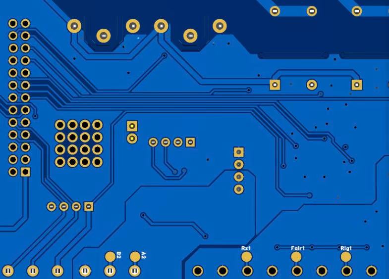
Before delving into its broader influence, it is essential to define precisely what In-Circuit Test entails. The In-Circuit Test is a method of verifying that each component on a PCB is correctly placed, soldered, and electrically functional. Unlike functional testing, which evaluates the PCB as a complete operational unit, ICT isolates and tests individual components and electrical networks to ensure they meet specific electrical parameters.
At its core, ICT operates by applying a controlled electrical signal to specific nodes of a circuit through a bed-of-nails test fixture or a flying probe system. Each probe contacts a designated test point, allowing measurement of resistance, capacitance, inductance, and continuity. The system compares the measured values with predefined limits derived from the design specifications. Deviations beyond acceptable tolerances indicate potential faults such as:
Open circuits: Missing or cracked solder joints preventing current flow.
Short circuits: Unintended connections between conductive paths.
Incorrect component values: Misplaced resistors, capacitors, or ICs.
Polarity or orientation errors: Reversed diodes or ICs leading to functional failures.
Solder bridges or insufficient solder: Affecting long-term reliability.
Modern ICT systems integrate boundary-scan testing, digital vector testing, and powered testing for dynamic validation of logic devices and microcontrollers. The result is a multi-dimensional view of board integrity—covering both static and active electrical performance.
ICT depends on the concept of electrical accessibility. Test engineers define test nodes strategically during PCB design to ensure sufficient coverage. The greater the number of accessible nodes, the higher the test coverage—but also the higher the fixture complexity and cost. Striking the right balance is crucial: too few test points may lead to undetected defects, while too many may increase mechanical stress and raise manufacturing costs.
While AOI and AXI are primarily visual inspection techniques, ICT provides a quantitative electrical verification. It does not simply detect whether a solder joint exists—it verifies whether it functions correctly. This distinction is what gives ICT its diagnostic precision. In industries such as automotive, aerospace, and medical electronics, where failure tolerance is virtually zero, ICT serves as a non-negotiable stage of the manufacturing pipeline.

In-Circuit Test
The In-Circuit Test performs several indispensable functions in the PCB production chain, each contributing to the ultimate goal of producing reliable and consistent electronics. Its scope extends from component-level validation to system-level assurance, offering manufacturers a detailed understanding of electrical performance.
During the early stages of assembly, issues such as poor soldering, component misplacement, or contamination can result in open or short circuits. ICT enables early detection of these defects before boards reach final functional testing. Early correction not only reduces scrap rates but also prevents defective boards from consuming valuable rework resources downstream.
This preventive detection plays a similar role to quality control checkpoints in pharmaceutical manufacturing—catching deviations before they compromise the entire batch. For high-volume manufacturers, this efficiency directly translates into improved production throughput and profitability.
Electrical reliability depends on more than correct assembly—it requires the assurance that each connection maintains stable performance over time. Through its precise measurement of resistance and continuity, ICT identifies weak joints and borderline components that could fail under stress or temperature variations. By pinpointing these vulnerabilities, manufacturers can enhance design rules and assembly practices, effectively creating a feedback loop for continuous improvement.
Moreover, when combined with statistical process control (SPC) tools, ICT results can be analyzed to detect systematic production trends. This data-driven insight allows engineering teams to adjust solder profiles, optimize paste deposition, or recalibrate pick-and-place equipment.
Functional testing simulates the actual operating environment of a PCB, which is time-consuming and resource-intensive. ICT acts as a complementary gatekeeper—filtering out electrically defective boards before they reach functional testing. By ensuring that only electrically sound assemblies proceed, ICT reduces the time and complexity required for final verification.
In industries that demand large-scale throughput, this layered testing strategy is vital for maintaining production velocity without compromising quality.
Manufacturing yield—the ratio of functional products to total production—is one of the most critical performance indicators for PCB manufacturers. A high yield not only reduces material waste but also enhances customer satisfaction and brand reputation. ICT contributes to yield improvement in several ways:
Root Cause Identification: ICT results offer traceability to specific process steps, allowing targeted corrective actions.
Process Optimization: Historical ICT data can highlight recurring issues tied to particular component footprints, solder types, or reflow profiles.
Reduced Field Failures: By ensuring each unit’s electrical integrity before shipment, ICT dramatically reduces warranty claims and post-sale maintenance.
Lower Rework Rates: Accurate fault localization simplifies repair, reducing both labor time and production costs.
In modern lean manufacturing environments, ICT has become a cornerstone of zero-defect strategy. It does not merely identify what went wrong; it explains why and where the process needs improvement.
The role of In-Circuit Test extends far beyond detecting faulty boards—it serves as the foundation of comprehensive quality assurance systems in PCB manufacturing.
Every ICT measurement generates traceable data linked to specific serial numbers, time stamps, and process stages. This data forms a digital quality record, allowing manufacturers to trace defects back to their origin. When customers report field failures, these records help identify whether the root cause originated from assembly, component quality, or environmental stress.
By maintaining such traceability, manufacturers can reduce warranty risks and demonstrate compliance with industry standards such as ISO 9001, IATF 16949, and IPC-A-610.
ICT’s diagnostic reports provide a valuable feedback mechanism for process improvement. For instance:
If repeated open circuits occur in the same area, engineers can investigate stencil thickness or solder paste viscosity.
If resistive values drift consistently, the component vendor or reel storage environment might be reviewed.
These feedback loops foster a culture of continuous improvement, transforming ICT from a cost center into a productivity asset.
In regulated industries such as medical electronics or automotive safety systems, ICT serves as documented evidence that each product meets electrical integrity standards. This traceable verification supports product certifications and reduces audit complexity.
| Category | Advantages of In-Circuit Test (ICT) | Disadvantages of In-Circuit Test (ICT) |
|---|---|---|
| 1. Fault Coverage | Offers high fault detection rate—can identify shorts, opens, wrong components, and value drift at the component level. | Cannot detect functional or timing-related faults, since it only tests static electrical properties. |
| 2. Diagnostic Accuracy | Provides precise fault localization, pinpointing the exact component or net that failed. | May produce false fails due to fixture contact issues or component tolerances. |
| 3. Repair Efficiency | Accelerates troubleshooting and repair because failures are clearly mapped to test nodes. | Fixture maintenance and calibration require additional time and skilled labor. |
| 4. Production Throughput | Can be fully automated, supporting high-speed testing in large-scale manufacturing. | Fixture changeover between different PCB designs reduces line flexibility. |
| 5. Integration with Quality Systems | Generates quantitative defect data that can be used for process control and yield improvement. | Data interpretation can be complex; requires experienced engineers for root cause analysis. |
| 6. Cost Perspective | Reduces rework and warranty costs by catching early assembly defects before shipment. | Initial investment for fixtures, software, and test setup can be high—less economical for low-volume runs. |
| 7. Test Accessibility | Excellent for through-hole and standard SMT assemblies with sufficient test pads. | Limited access on high-density or microvia PCBs where probe landing is difficult. |
| 8. Design for Testability (DFT) | Encourages better PCB design practices by enforcing test point allocation and layout discipline. | Adds design constraints—extra space for test pads may conflict with miniaturization goals. |
| 9. Reliability Impact | Ensures long-term electrical integrity, preventing latent defects from reaching customers. | Repeated probing can cause mechanical stress on fragile or flex circuits if not properly managed. |
| 10. Adaptability to Modern Trends | Evolving with AI, boundary-scan, and digital twin technologies for smart diagnostics. | Legacy ICT systems may struggle with high-frequency or multilayer RF boards without major upgrades. |
In the intricate world of electronics, where microscopic misalignments can render entire systems dysfunctional, In-Circuit Test stands as the conscience of modern manufacturing. It ensures that every board leaving the factory represents a truthful realization of the design engineer’s intent.
Beyond its electrical precision, ICT embodies a deeper philosophy—a commitment to integrity, transparency, and continuous improvement. It bridges design ideals and production realities, connecting engineering vision with measurable truth.
As electronics continue to evolve toward greater density, complexity, and performance demands, the role of ICT will expand in tandem. Manufacturers that treat ICT as a strategic pillar rather than a procedural step—like JM PCB—will not only deliver superior quality but also cultivate lasting trust among customers worldwide.
Ultimately, the In-Circuit Test is not just about circuits and measurements; it is about responsibility. It reflects an industry’s ongoing promise to deliver reliability, precision, and safety—one board at a time.
An In-Circuit Test checks the individual components and interconnections on a PCB to verify that they are correctly assembled and electrically sound. A Functional Test evaluates the fully assembled board in an operating environment to ensure it performs as intended. ICT isolates faults at the component level, while functional testing verifies overall system behavior.
ICT directly improves manufacturing yield by identifying defects early in the production line. By catching open circuits, shorts, or incorrect components before functional testing, it prevents defective boards from consuming further resources. The result is fewer reworks, higher first-pass yield, and lower total production cost.
The most significant limitation of ICT is test access. As PCB designs become denser, there are fewer available test pads. Fixture costs can also be high for complex or low-volume designs. However, technologies such as flying probe testers and boundary-scan testing are effectively mitigating these challenges.
Yes. Modern ICT systems can verify the correct orientation and polarity of components such as diodes, capacitors, and integrated circuits. Through precision measurement and controlled signal application, the system confirms that each component is installed correctly, reducing the risk of functional failure.
Yes. Modern ICT systems can verify the correct orientation and polarity of components such as diodes, capacitors, and integrated circuits. Through precision measurement and controlled signal application, the system confirms that each component is installed correctly, reducing the risk of functional failure.
Connect to a Jerico Multilayer PCB engineer to support your project!
Request A Quote