


+86 13603063656
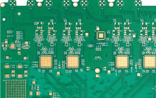
In the evolving landscape of modern defense systems, Military Circuit Boards represent the nerve center of advanced technologies that define national security. These boards are not merely carriers of electronic components—they are mission-critical infrastructures designed to perform under extremes of temperature, vibration, electromagnetic interference, and unpredictable operational stresses.
Unlike commercial or consumer-grade electronics, which may operate within narrow environmental tolerances, Military Circuit Boards are built with uncompromising standards. Every layer of material selection, manufacturing precision, and quality control reflects a pursuit of resilience and reliability. Their role extends from controlling guided missile systems and radar platforms to enabling satellite communications and unmanned aerial vehicles.
As technology evolves, the dominance of a military force is closely linked to the engineering sophistication of Military Circuit Boards. They represent not just hardware, but the strategic advantage of ensuring that electronic systems do not falter, even in the harshest battlefields.
Military Circuit Boards
The origins of Military Circuit Boards trace back to the post-World War II era, when militaries worldwide recognized that miniaturization and integration of electronics were essential to achieve battlefield superiority. Early designs were simple, often single-layer boards with minimal complexity. Their main purpose was to support radios, simple navigation tools, and communication systems.
However, these boards lacked the thermal resistance, vibration endurance, and signal integrity required in evolving defense platforms. As aerospace engineering and missile guidance systems demanded more sophisticated electronics, the evolution of Military Circuit Boards accelerated.
The shift from rigid, single-layer designs to multi-layer Military Circuit Boards marked a breakthrough. Multi-layer boards allowed for denser circuitry, greater power handling, and better shielding from electromagnetic interference. Technologies like blind vias, buried vias, and advanced surface finishes expanded the functionality of these boards.
Today, we see hybrid designs that combine rigid and flexible substrates, enabling engineers to create compact yet resilient systems that can withstand mechanical stresses in aircraft, submarines, and armored vehicles.
The superiority of Military Circuit Boards lies not only in their construction but in the unique benefits they offer when exposed to challenging operational conditions.
Thermal Stability: Able to operate across wide temperature ranges without signal degradation.
Vibration Resistance: Reinforced solder joints and embedded vias ensure boards remain intact under constant mechanical stress.
Moisture & Corrosion Resistance: Protective coatings such as conformal coatings or parylene films prevent chemical damage.
Military equipment may remain in service for decades, unlike commercial devices that are replaced every few years. Military Circuit Boards are therefore engineered for long-term availability of materials, repairability, and backward compatibility.
Combat environments demand:
High-speed data transfer for real-time situational awareness.
Power management stability for energy-intensive radar or directed-energy systems.
Signal integrity in electronic warfare, where interference is deliberately deployed.
These stringent requirements ensure that Military Circuit Boards act as the backbone of mission assurance.
Aerospace is perhaps the most demanding application field for Military Circuit Boards. Aircraft, spacecraft, and drones all rely on advanced PCBs to manage avionics, navigation, and weapon systems. The boards used in this domain must withstand:
High altitude and low pressure: Rapid changes in atmospheric pressure can lead to expansion or contraction of board materials. Polyimide-based boards with low coefficient of thermal expansion (CTE) are preferred.
Extreme vibration and shock: Fighter jets and attack helicopters generate tremendous vibration. Military-grade PCBs often include thicker copper layers, reinforced vias, and rigid-flex combinations to survive these stresses.
Electromagnetic interference (EMI): Aircraft are surrounded by radar and communication signals. EMI shielding layers and carefully routed controlled impedance lines are crucial for maintaining reliable communications and radar accuracy.
In modern stealth aircraft, Military Circuit Boards not only serve as electronic backbones but also contribute to lightweight design strategies. Engineers integrate rigid-flex PCBs into curved surfaces of aircraft fuselage to save weight and reduce space requirements.
Naval defense platforms—submarines, destroyers, and aircraft carriers—present a unique challenge to Military Circuit Boards.
Moisture and Salt Spray: Saltwater corrosion is one of the most aggressive environmental threats. Boards must be coated with conformal layers such as parylene to prevent ionic contamination.
Shock Resistance: When naval ships fire missiles or are exposed to undersea explosions, shock waves propagate through electronic equipment. Military boards are mounted with rugged connectors and mechanically reinforced housings.
Long-Term Reliability: Naval systems often stay deployed at sea for months without resupply. A failure in a radar or sonar circuit board can compromise mission safety. Thus, military PCBs undergo accelerated lifecycle testing.
Sonar systems, missile launch platforms, and navigation units all depend on Military Circuit Boards that can function flawlessly in humid, corrosive marine environments.
Armored vehicles, tanks, and mobile artillery systems also employ Military Circuit Boards for fire control, communication, and engine management. Ground conditions pose unique hazards:
Dust and Sand: Boards must be enclosed with dust-proof and vibration-resistant enclosures.
Shock and Recoil: When heavy artillery is fired, vibrations and shockwaves threaten solder joints and connectors. Reinforced soldering and embedded vias reduce risk of micro-cracks.
Temperature Extremes: Desert operations can reach +70°C, while arctic missions may plunge below −40°C. Boards must survive such thermal cycling without delamination.
Modern armored vehicles increasingly rely on digital battlefield networking, where every unit communicates in real-time. The reliability of Military Circuit Boards ensures seamless integration with command-and-control systems.
Space presents the harshest test of Military Circuit Boards. Satellites, deep space probes, and orbital defense platforms face:
Radiation: Cosmic rays and solar storms can damage semiconductor devices. Boards must incorporate radiation-hardened components.
Thermal Vacuum Conditions: With no atmosphere, boards alternate between scorching heat in direct sunlight and freezing cold in shadow. Metal-core substrates help dissipate thermal loads.
Longevity: Satellites may operate for 15+ years without repair. Thus, boards must not only function but also age predictably.
Here, Military Circuit Boards embody the principle of engineering for permanence. A single failure in orbit may cost billions and jeopardize critical defense communication.
Looking ahead, Military Circuit Boards are enabling:
Directed Energy Weapons (DEWs): High-power laser and microwave systems require boards with superior thermal conductivity and precise impedance control.
Electronic Warfare (EW): Boards designed to operate in contested electromagnetic environments, often with adaptive filtering and rapid response capabilities.
Unmanned Systems (UAVs and UGVs): Light, compact, and durable PCBs are key to drones and ground robots, which must balance weight reduction with high reliability.
These applications underscore the strategic importance of Military Circuit Boards in shaping the future of warfare.
Designing Military Circuit Boards goes beyond typical PCB engineering. Every decision—from material choice to trace routing—must accommodate extreme environmental and operational stresses. Key challenges include:
High-power components in radar, guided missiles, and directed energy weapons generate significant heat. Without proper thermal management, boards may delaminate, traces may lift, or components may fail. Solutions include:
Metal Core PCB Substrates: Improve heat dissipation while maintaining structural integrity.
Thermal Vias and Heat Sinks: Enable effective heat transfer from components to the board surface or chassis.
Advanced Thermal Simulation: Engineers model thermal profiles to predict hotspots and ensure safe operation across −55°C to +200°C.
Modern military electronics often operate at GHz frequencies. Poor signal integrity can compromise radar, communications, or electronic warfare systems. Design considerations include:
Controlled Impedance Lines: Ensures minimal signal distortion.
Differential Pair Routing: Reduces electromagnetic interference (EMI) and crosstalk.
Shielding Layers: Protect sensitive circuits from external and internal EMI sources.
Military boards must survive shocks from explosions, recoil, or transportation:
Rigid-Flex Designs: Combine flexible circuits with rigid layers to absorb mechanical stress.
Embedded Vias and Reinforced Pads: Prevent micro-cracks in critical signal paths.
Shock Absorbing Mounts: Reduce stress transferred from the vehicle or aircraft to the PCB.
Material choice is critical:
Polyimide Laminates: Excellent high-temperature performance but costly and harder to process.
High-Tg FR4: More economical but may require additional coatings for thermal resistance.
Metal Core: Ideal for high-power applications, but thicker and heavier.
The balance between weight, cost, manufacturability, and performance defines the success of Military Circuit Boards in real-world applications.
To meet these challenges, engineers have introduced several innovative technologies:
Surface finishes improve solderability, corrosion resistance, and durability:
ENIG (Electroless Nickel Immersion Gold): Protects traces from oxidation, suitable for high-reliability assemblies.
Hard Gold Plating: Ideal for edge connectors that undergo repeated mating cycles.
OSP (Organic Solderability Preservatives): Cost-effective option for boards requiring moderate environmental resistance.
Blind and Buried Vias: Increase routing density while saving board space.
High-Density Interconnect (HDI): Enables compact military electronics with complex functionality.
Rigid-flex boards allow folding or bending without breaking traces, essential for drones, satellites, and confined vehicle compartments.
Emerging boards integrate passive or even active components within the PCB itself, improving size, weight, and reliability. This is particularly valuable in aerospace or miniature unmanned systems.
Different operational environments impose distinct performance criteria on Military Circuit Boards:
| Environment | Key Requirements | Example Applications |
|---|---|---|
| Aerospace | Thermal cycling, EMI shielding, vibration resistance | Fighter jets, drones, satellites |
| Naval | Moisture & salt resistance, shock resistance | Submarines, destroyers, sonar systems |
| Ground Vehicles | Dust & vibration resistance, high-temp tolerance | Tanks, mobile artillery |
| Space | Radiation hardening, thermal vacuum performance | Satellites, deep-space probes |
| Electronic Warfare | High-frequency signal integrity, rapid response | EW modules, radar jamming units |
The design philosophy is always “failure is not an option”, which differentiates military-grade PCBs from commercial alternatives.
Producing Military Circuit Boards is a meticulous process that combines advanced materials, precise engineering, and stringent quality assurance. Unlike commercial PCBs, where minor defects may be tolerated, military boards demand zero-compromise reliability.
The choice of materials defines both performance and durability:
Substrates
Polyimide: High-temperature and flexible applications.
High-Tg FR4: Cost-effective, suitable for moderate thermal and mechanical stress.
Metal Core: Dissipates heat for high-power components.
Copper Foil
Rolled Copper Foil: Offers superior mechanical strength and surface quality, ideal for high-reliability applications.
Electrolytic Copper Foil: Flexible, cost-effective, suitable for less mechanically stressed areas.
Laminates and Prepregs
Used to bond layers, providing mechanical strength, thermal stability, and insulation.
Controlled CTE ensures minimal warpage during thermal cycling.
The layer stack-up is carefully engineered to balance signal integrity, thermal dissipation, and mechanical stability. Multilayer boards may exceed 20 layers, with blind or buried vias for dense routing.
Circuit Patterning
Photolithography and etching create precise copper traces.
Advanced processes allow microvias and HDI routing.
Drilling and Via Formation
Laser or mechanical drilling creates plated through-holes.
Embedded vias enhance signal integrity and reduce board size.
Surface Finishing
ENIG, hard gold, or OSP coatings are applied for solderability and environmental resistance.
Solder Mask and Silkscreen
High-temperature solder masks protect traces from oxidation and shorts.
Accurate silkscreening supports assembly and inspection.
Assembly Readiness
Boards are tested for flatness, thickness, and alignment to ensure precise component placement.
Quality control is paramount:
Automated Optical Inspection (AOI): Detects surface defects, misalignments, and incomplete etching.
X-ray Inspection: Verifies via fill, solder integrity, and internal layers.
Thermal Cycling Tests: Simulates extreme temperature swings to detect delamination or warpage.
Vibration and Shock Testing: Confirms mechanical durability under operational stresses.
Electrical Testing: Checks continuity, impedance, and signal integrity for mission-critical circuits.
This exhaustive testing ensures that every Military Circuit Board can survive operational extremes without compromising performance.
Traceability: Materials and processes are documented for full traceability.
MIL-SPEC Compliance: Boards must meet MIL-PRF-31032 and IPC Class 3 standards.
Vendor Collaboration: High-reliability boards often require close coordination with suppliers for materials like polyimide laminates or specialized copper foils.
Military Circuit Boards have evolved from simple single-layer assemblies to highly sophisticated multi-layer, rigid-flex, and high-density interconnect designs. They are the backbone of modern defense systems, providing mission-critical reliability in the harshest environments—ranging from aerospace and naval platforms to ground vehicles and space applications.
Uncompromising Reliability
Military-grade PCBs are engineered to withstand extreme temperatures, vibration, moisture, and radiation, ensuring electronic systems remain operational when lives and national security depend on them.
Material and Design Excellence
Polyimide laminates, high-Tg FR4, and metal cores provide thermal and mechanical resilience.
Rolled copper foil offers superior strength, while electrolytic copper foil provides flexibility and cost-effectiveness.
Advanced surface finishes like ENIG and hard gold plating enhance solderability and corrosion resistance.
Technological Innovations
Emerging technologies, including HDI, rigid-flex integration, embedded components, and thermal management strategies, continue to push the performance boundaries of Military Circuit Boards.
Application-Specific Adaptation
Boards are tailored to their operating environment, ensuring reliability in aerospace, naval, ground, and space systems, as well as electronic warfare and unmanned systems.
Quality Assurance and Standards Compliance
Compliance with MIL-SPEC, IPC Class 3, and AS9100 ensures boards meet the highest standards of performance and reliability. Rigorous testing protocols—thermal, vibration, shock, and electrical—verify that boards can endure mission-critical stresses.
As defense technology continues to advance, the demand for smaller, lighter, and more resilient Military Circuit Boards will increase. Emerging trends include:
Integration of AI and advanced sensors directly into the PCB for faster data processing.
Next-generation thermal management solutions to handle increasingly high-power components.
Miniaturization for drones, satellites, and portable battlefield systems.
Sustainability and recyclability in materials, reducing environmental impact without compromising performance.
Defense systems of the future will rely heavily on Military Circuit Boards not only for their electronic capabilities but also for their durability and adaptability, ensuring operational dominance across all environments.
Rolled copper foil is produced by mechanically rolling copper into thin sheets, offering better surface quality and mechanical strength, making it ideal for high-reliability and high-stress applications such as aerospace or missile systems.
Electrolytic copper foil, on the other hand, is deposited via an electrolytic process, providing more flexibility and being more cost-effective. It is suitable for applications with less mechanical stress or where cost is a primary concern.
Polyimide laminates exhibit excellent thermal stability, withstanding temperatures from −55°C up to +200°C, and possess high chemical resistance. They are also flexible, enabling rigid-flex designs, which is crucial for aircraft, drones, and satellites where boards must fit into compact or moving assemblies.
ENIG (Electroless Nickel Immersion Gold) provides a corrosion-resistant and solderable surface, protecting copper traces from oxidation. It ensures reliable long-term connections, critical in high-reliability military applications where maintenance opportunities are limited.
Military-grade boards undergo a rigorous suite of tests, including:
Thermal cycling for extreme temperature resistance.
Vibration and shock testing for mechanical durability.
X-ray inspection for internal layer and via integrity.
Electrical testing for continuity, impedance, and signal integrity.
These procedures ensure boards perform reliably in aerospace, naval, ground, or space environments.
Rigid-flex designs integrate flexible circuits with rigid substrates, allowing boards to fold or bend without breaking traces. This design reduces weight, saves space, and increases durability under mechanical stress, making it ideal for drones, satellites, and compact military devices.


Connect to a Jerico Multilayer PCB engineer to support your project!
Request A Quote


 Quote
Quote