


+86 13603063656
The study of electricity has always been guided by fundamental principles that govern the movement of charges. Among these principles, none is more central to practical circuit design than the inverse relationship between resistance and current. Engineers, scientists, and educators alike often emphasize this interplay because it defines how energy flows, how circuits behave under varying loads, and how efficiency can be optimized. Resistance and current are not isolated concepts; rather, they form a dialectical pair, in which the increase of one directly affects the decrease of the other.
When we examine this opposition in depth, it becomes clear that the relationship between resistance and current is not simply a mathematical abstraction. It represents a profound truth about the behavior of electrons in conductive pathways. The inverse correlation forms the backbone of Ohm’s Law, but it also extends far beyond basic formulas into the real-world applications of circuit design, from consumer electronics to aerospace systems.
In this article, I aim to provide a comprehensive exploration of this relationship, beginning with the foundations of resistance and current, moving through their mathematical and material properties, and then reflecting on their benefits and implications for printed circuit boards (PCBs). I will also incorporate my own reflections as someone who believes that electrical engineering is as much a field of philosophy as it is of science: to understand resistance and current is to understand balance, compromise, and design wisdom.
Before diving into technical details, it is worth remembering that these concepts are not just theoretical constructs. They are practical, measurable, and manipulable parameters that dictate whether a smartphone charges properly, whether a satellite maintains communication, and whether industrial machines run efficiently. By tracing their roots and exploring their applications, we may gain new insights into why resistance and current remain the great opposition in electronics.
resistance and current
The scientific discovery of resistance and current stretches back to the 18th and 19th centuries, when figures like Georg Simon Ohm and Alessandro Volta laid the foundations of modern electrical theory. Ohm’s publication in 1827, Die galvanische Kette, mathematisch bearbeitet, provided not just an experimental observation but a mathematical framework that would unify voltage, resistance, and current into a law that remains essential to this day.
From a historical perspective, the relationship between resistance and current shaped the trajectory of technological advancement. Telegraph lines in the 19th century had to account for resistance over long distances, as signal strength diminished with increasing resistance. Later, in the 20th century, as consumer electronics and computing developed, resistance became a tool for regulating and controlling current, ensuring that delicate transistors received exactly the right operating conditions.
The history also reveals an evolving understanding of materials. Initially, copper and iron wires were the most common conductors, but soon, researchers discovered that temperature, impurities, and fabrication methods significantly influenced resistance. Modern materials such as superconductors, which exhibit zero resistance under certain conditions, are a continuation of this quest to manipulate the interplay between resistance and current.
Reflecting on this history, one realizes that the opposition between resistance and current is not just theoretical—it has always been a driver of invention, shaping how humans harness electricity for communication, computation, and industrial progress.
At a microscopic level, resistance and current can be explained in terms of electron dynamics. Conductive materials, such as metals, contain free electrons that can move through the atomic lattice. When a voltage is applied, it creates an electric field that pushes electrons forward. Current results from this drift motion.
However, electrons do not move unimpeded. They collide with atoms, lattice imperfections, and other electrons. Each collision dissipates energy, often in the form of heat, and this dissipation is what we call resistance.
Different materials have different intrinsic resistivities. Copper, for example, has a low resistivity, making it ideal for wires and PCBs. Nichrome, with higher resistivity, is useful for resistive heating elements. The interplay between resistance and current, therefore, is highly dependent on material choice—a fact that directly informs PCB design and manufacturing.
It is here that I find myself reflecting on the elegance of nature’s laws: resistance is not a flaw but a feature. Without resistance, we could not regulate current. Without current, resistance would be meaningless. Together, they create an equilibrium that engineers must respect and manipulate.
While resistance and current are often framed in opposition, their relationship offers multiple benefits for engineers. Properly balancing these factors allows for:
Control of Power Dissipation – Resistance limits current flow, preventing overheating and protecting sensitive components.
Signal Conditioning – In analog circuits, resistors help shape signals, filter noise, and set biasing points.
Energy Efficiency – Optimizing resistance ensures that current flows where needed, reducing unnecessary losses.
Safety – Controlled resistance prevents dangerous surges of current that could damage devices or harm users.
Customization – Engineers can design circuits with desired resistance-current characteristics to suit applications ranging from low-power sensors to high-power industrial drives.
For companies engaged in PCB manufacturing, understanding the inverse relationship between resistance and current is critical. PCBs are the backbone of electronic devices, and their material properties, trace widths, and copper thickness all determine resistance, which in turn dictates how much current can flow safely.
The relationship between resistance and current is not only a matter of physics but also a domain governed by precise mathematical laws. While Ohm’s Law serves as the foundation, additional mathematical tools and principles help engineers analyze, predict, and manipulate electrical behavior. These equations give clarity to design, ensuring that circuits function reliably and efficiently.
Here, the inverse relationship between resistance and current is explicit. For a constant voltage source, doubling the resistance halves the current. Likewise, halving the resistance doubles the current. This proportionality is linear under ideal conditions and forms the core of almost every circuit analysis.
However, Ohm’s Law is not merely an equation—it is a design philosophy. It forces engineers to think critically about trade-offs. For example, increasing resistance may protect sensitive devices from excessive current, but it also reduces the energy delivered to loads. On the other hand, reducing resistance improves efficiency but risks overheating.
In my reflection, I find that Ohm’s Law mirrors the kind of balance required in life: too much restriction and flow is stifled, too little restriction and chaos ensues.
Ohm’s Law alone cannot describe complex circuits. That is where Kirchhoff’s Circuit Laws come into play:
Kirchhoff’s Current Law (KCL): The sum of currents entering a node is equal to the sum of currents leaving it.
Kirchhoff’s Voltage Law (KVL): The sum of voltage drops around any closed loop in a circuit is equal to zero.
When combined with Ohm’s Law, these rules allow engineers to analyze even the most complex PCB networks containing thousands of resistors, capacitors, and active devices.
For example, in a PCB power distribution network, KCL ensures that the total current drawn by different components does not exceed the capacity of supply traces. Similarly, KVL guarantees that all resistive drops along traces still deliver the correct voltage levels to IC pins.
Thus, the inverse relationship between resistance and current is embedded within these broader conservation principles, showing that mathematics not only quantifies but also unifies circuit behavior.
While Ohm’s Law assumes linearity, real-world components often behave nonlinearly. For instance:
Semiconductors such as diodes and transistors do not follow a simple proportionality between current and voltage. Their resistance changes dynamically depending on biasing conditions.
Thermistors change resistance with temperature, meaning current flow is self-regulating in some contexts.
Superconductors exhibit zero resistance below critical temperatures, leading to effectively infinite current capacity under proper constraints.
These nonlinear cases show that the opposition between resistance and current is not always straightforward. Mathematical models, often involving exponential or polynomial relationships, are required to accurately predict performance.
I find this nonlinearity fascinating because it mirrors the complexity of real life. Just as human behavior does not always follow linear cause-and-effect rules, electrical systems too reveal unexpected dynamics that resist oversimplification.
If Ohm’s Law gives us the mathematical foundation of resistance and current, then material science reveals the physical reality that underlies those equations. The behavior of resistance and current is profoundly influenced by the atomic structure, composition, and processing of materials. Engineers and PCB designers must understand these influences in order to build circuits that are reliable, efficient, and long-lasting.
In this section, I will explore how various materials—from traditional metals like copper and aluminum to modern composites and superconductors—shape the inverse relationship between resistance and current. I will also reflect on how these material choices manifest in PCB technology and everyday applications.
The intrinsic property known as resistivity (ρ) is the cornerstone of material influence on resistance and current. Resistivity is a material constant that defines how strongly a material opposes the flow of electric charge.
Metals like copper (ρ ≈ 1.68 × 10⁻⁸ Ω·m) and silver (ρ ≈ 1.59 × 10⁻⁸ Ω·m) are excellent conductors because they have low resistivity. This means that for a given voltage, they allow a higher current to pass through with minimal resistance. By contrast, materials like rubber or glass have extremely high resistivity, functioning as insulators that block current almost entirely.
In practical terms, resistivity determines the thickness and width of conductors required in a PCB. For high-current applications, designers often prefer copper because its low resistivity ensures manageable trace sizes without excessive heat generation.
This reinforces the inverse relationship: choosing materials with low resistivity reduces resistance, thereby increasing current capacity. Conversely, high-resistivity materials restrict current, serving roles as insulators or resistors.
One of the most significant material science factors influencing resistance and current is temperature dependence.
For most conductive materials, resistance increases with temperature. This is because as the lattice vibrates more energetically, electrons encounter more collisions, raising resistance and reducing current for a given voltage.
From a PCB perspective, this is critical. High current flowing through thin traces can raise local temperatures, increasing resistance further, leading to more heating—a vicious cycle that can cause thermal runaway. Engineers must therefore account for both static resistance and its dynamic behavior under operating conditions.
Interestingly, semiconductors behave differently. Their resistance decreases with increasing temperature, making them useful in temperature-sensing applications. Thermistors are a prime example: Negative Temperature Coefficient (NTC) thermistors drop resistance as temperature rises, allowing engineers to exploit this nonlinear resistance-current behavior for monitoring and protection.
At high frequencies, material surface properties become critically important. The skin effect causes current to flow mainly on the surface of conductors rather than through the entire cross-sectional area. This makes surface roughness a major determinant of effective resistance.
For PCBs carrying high-frequency signals, rough copper foil increases effective resistance, attenuating signals and distorting performance. Smooth rolled copper foil provides superior conductivity in high-speed applications compared to electrolytic copper foil, which is typically rougher.
This example highlights the subtle but powerful influence of materials science on the balance of resistance and current. Two boards with the same nominal copper thickness can behave very differently depending on the microscopic texture of the copper surface.
Pure metals are not always ideal. Engineers often rely on alloys and composites to fine-tune resistance and current characteristics.
Nichrome (Nickel-Chromium Alloy): Widely used in heating elements because it offers relatively high resistance, stability at elevated temperatures, and predictable performance.
Constantan (Copper-Nickel Alloy): Used in precision resistors and strain gauges because its resistance remains stable across a wide range of temperatures.
Carbon Composites: Offer higher resistance than metals, used in resistor elements, but still conductive enough for controlled current flow.
These materials show that resistance and current can be engineered, not just observed. By blending elements, one can tailor conductivity, thermal stability, and durability.
The relationship between resistance and current is not confined to theoretical equations or laboratory demonstrations. It lives and breathes in every practical circuit design decision engineers make. Whether developing simple household electronics, designing critical aerospace systems, or fabricating multilayer printed circuit boards (PCBs), the interplay between resistance and current determines performance, safety, and longevity.
In this section, I will explore a range of practical applications where resistance and current are deliberately manipulated to achieve desired outcomes. I will also reflect on the ways these applications reveal both the versatility and inevitability of the great opposition between resistance and current.
Perhaps the most visible role of resistance and current in practical electronics is in power regulation.
Voltage Dividers: By arranging resistors in series, engineers can reduce voltage levels to suit delicate components. The current flowing through the divider is controlled by the resistance values chosen. Without resistance, current would flow unimpeded, making voltage division impossible.
Current Limiting: Resistors are often placed in series with LEDs or transistors to limit current and prevent damage. An LED, for example, may require only 20 mA of current. Without a resistor, the current from a 5V source could exceed this, burning out the LED.
Power Dissipation: In high-power systems, resistors are used as load banks to safely dissipate energy. Here, the quadratic relationship P=I2RP = I^2R becomes essential for calculating how much heat must be managed.
In all these cases, the opposition between resistance and current is not a limitation but a tool. Resistance acts as a gatekeeper, shaping current into usable, safe, and effective flows.
Another critical application is signal conditioning, where resistance and current are manipulated to shape electrical signals for transmission, measurement, or processing.
Biasing of Transistors: Resistors set the correct operating point for transistors, ensuring stable amplification. The resistor values determine the current drawn, which directly influences signal gain and distortion.
Filters: Together with capacitors or inductors, resistors form low-pass, high-pass, or band-pass filters. These circuits rely on resistance to control current flow across frequency ranges, eliminating noise or isolating desired signals.
Analog-to-Digital Converters (ADCs): Resistor ladders create precise voltage steps that allow digital systems to interpret analog signals. Without stable resistance, current levels would fluctuate, leading to inaccurate conversions.
For PCB design, these applications demand precise control of trace resistance, as even minor variations can affect signal integrity in high-speed circuits. Engineers often collaborate closely with manufacturers to ensure that resistance values across traces remain within tight tolerances.
One of the most practical benefits of resistance and current is their use in protection mechanisms.
Fuses and Current-Sensing Resistors: By designing resistors that heat up and melt at specific currents, engineers create fuses that protect devices from overloads.
Shunt Resistors: Low-value resistors are used to sense current in real-time, enabling overcurrent protection circuits. The voltage drop across the resistor is proportional to current, allowing microcontrollers to monitor and respond.
Electrostatic Discharge (ESD) Protection: Resistors can slow down current surges, preventing sensitive semiconductor junctions from being destroyed.
These examples show that resistance and current, when carefully balanced, serve as guardians of circuit longevity. The “opposition” between them is leveraged as a shield against unpredictability.
Sometimes, engineers exploit resistance explicitly to generate heat.
Resistive Heaters: Devices like electric stoves, toasters, and hair dryers use coils of high-resistance wire (often Nichrome). As current passes through, resistance converts electrical energy into heat.
Defrosting Circuits: Automobile rear windows and some refrigeration systems use resistive films to generate heat for defrosting or de-icing.
Medical Devices: Controlled resistive heating is used in surgical tools or therapy devices where precision is vital.
Here, the inverse relationship is central: increasing resistance for a fixed voltage reduces current but increases energy dissipation per unit length, allowing engineers to design heaters of specific power outputs.
In modern communication systems, high-frequency performance is paramount. At these frequencies, resistance and current interact in more complex ways due to phenomena like the skin effect and parasitic resistance.
RF Circuits: Resistors are used not only for biasing but also for impedance matching. Improper resistance leads to reflection of current signals, distorting data transmission.
PCB Design: Trace resistance, surface finish, and copper roughness all affect current distribution at high frequencies. Smooth rolled copper foil is preferred for GHz-range applications, as it minimizes resistance-induced signal loss.
Antennas: The efficiency of an antenna depends on carefully balancing radiation resistance with conduction losses. The design aims to maximize current radiation while minimizing resistive heating.
This area highlights how resistance and current interplay differently at scale, requiring engineers to think beyond DC and low-frequency approximations.
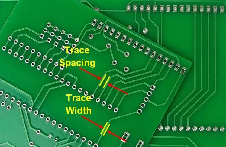
Printed circuit boards serve as the canvas upon which the balance of resistance and current is drawn. Practical design requires careful consideration of:
Trace Width: Wider traces reduce resistance, allowing higher current without overheating.
Copper Thickness: Increasing copper weight (e.g., from 1 oz/ft² to 2 or 3 oz/ft²) reduces resistance, improving current-carrying capacity.
Via Resistance: Vias connecting different PCB layers introduce additional resistance. Multiple vias in parallel reduce resistance and distribute current evenly.
Ground Planes: Large copper planes reduce resistance, ensuring stable current return paths and minimizing noise.
Thermal Relief: Proper resistance design avoids localized hot spots, which can damage components.
Manufacturers with strong engineering support, such as JM PCB, assist designers in balancing these factors. Their ability to deliver custom copper weights, precision etching, and multilayer structures ensures that resistance and current are controlled not only in theory but in production reality.
Throughout this extensive exploration, one theme has remained constant: resistance and current are far more than physical quantities. They are principles of life, technology, and thought. Their inverse relationship, captured in Ohm’s Law, illustrates a paradox that is both scientific and philosophical—too much current without resistance leads to chaos, while too much resistance without current leads to stagnation.
In science and engineering, resistance and current determine how our devices function, how energy is distributed, and how innovation continues to reshape our world. In education, they symbolize the flow of knowledge and the necessary challenges that give learning meaning. In society and personal growth, they emerge as metaphors for progress and limitation, ambition and discipline, change and tradition.
The lesson is clear: progress does not come from eliminating resistance, nor from amplifying current endlessly. It comes from their balance. Resistance tempers, shapes, and strengthens. Current energizes, motivates, and propels forward. Together, they create sustainable flow—whether in an electrical circuit, a classroom, or a human life.
Rolled copper foil is produced by mechanically rolling copper into thin sheets. This method yields superior surface quality, higher mechanical strength, and excellent ductility. It is ideal for high-frequency PCBs, flexible circuits, and environments where bending or mechanical stress is expected.
Electrolytic copper foil, on the other hand, is created through an electrolytic deposition process. It is generally more cost-effective and flexible, making it suitable for mainstream PCB applications where mechanical endurance is less critical.
In PCB design, resistance and current are central to trace width, material selection, and thermal management. High resistance generates heat, which can damage components if not dissipated properly. Adequate current flow is essential to power circuits reliably. Designers often use wider copper traces, heat sinks, or multilayer boards to manage this balance effectively. Partnering with reliable manufacturers such as JM PCB helps ensure that resistance and current parameters are optimized for both performance and safety.
In renewable systems like solar panels or wind turbines, controlling resistance and current ensures efficiency. Excessive resistance in conductors or storage systems reduces energy transfer, while uncontrolled currents can overload inverters or batteries. Proper design, including high-conductivity materials and intelligent control systems, maximizes output while maintaining safety and longevity.
For engineering students, understanding resistance and current provides:
A strong foundation for circuit theory and electronics.
Practical skills in analyzing and troubleshooting systems.
Insight into interdisciplinary applications, from biomedical devices to AI hardware.
Confidence in translating classroom concepts into real-world projects.
Educational tools, prototyping kits, and access to manufacturers like JM PCB help students bridge theory and practice, making learning more effective.
Yes. Resistance and current serve as powerful metaphors across disciplines:
In society: Current represents change, while resistance symbolizes tradition or inertia.
In personal growth: Current represents ambition or creativity, while resistance represents discipline or limitations.
In philosophy: Meaning emerges from the balance of flow and opposition.
These metaphors make the concepts of resistance and current not only scientifically vital but also deeply human.


Connect to a Jerico Multilayer PCB engineer to support your project!
Request A Quote


 Quote
Quote