


+86 13603063656
In the rapidly evolving world of high-frequency electronics, material selection has become a decisive factor that directly determines circuit performance, manufacturing reliability, and product longevity. Among the many specialized laminates available, Rogers 5880 Thickness Options stand out as a defining benchmark for consistency, low dielectric loss, and excellent high-frequency performance. For engineers designing RF, microwave, or millimeter-wave circuits, the material’s unique characteristics enable them to extract the maximum potential from their designs while ensuring that the performance is predictable and repeatable across temperature and frequency ranges.
The primary challenge in high-frequency PCB design lies not merely in routing or stack-up but in aligning electrical performance with mechanical feasibility. This is where Rogers 5880 Thickness Options make a critical difference. The ability to choose from various thicknesses allows designers to fine-tune parameters such as impedance, insertion loss, and phase stability, all while maintaining manufacturability and cost control. In practice, these thickness variations translate into improved matching between theoretical models and real-world circuit behavior.
What sets Rogers 5880 apart from conventional materials like FR-4 or even some PTFE composites is its extremely low dielectric constant (typically around 2.2) and an exceptionally low dissipation factor (approximately 0.0009 at 10 GHz). These characteristics make it one of the most trusted materials for radar systems, satellite communication modules, phased array antennas, and other high-precision RF applications. However, to fully exploit these advantages, engineers must understand the nuances of Rogers 5880 Thickness Options, their role in design optimization, and how to integrate them into a complete system solution.
The journey toward frequency optimization is as much about material knowledge as it is about system design philosophy. In this article, we take a deep technical and functional look at how different Rogers 5880 Thickness Options influence the performance of high-frequency systems, how designers can match the right configuration to specific applications, and how proper manufacturing practices—especially through experienced partners such as JM PCB—can ensure consistency and reliability.

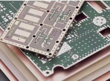
Rogers 5880 Thickness Options
At its core, Rogers 5880 is a PTFE (Polytetrafluoroethylene) composite reinforced with glass microfibers, a formulation designed to achieve a delicate balance between mechanical robustness and exceptional electrical stability. The microfibers serve to minimize deformation during lamination and etching, while the PTFE matrix ensures that the dielectric properties remain uniform across frequency bands.
The Rogers 5880 Thickness Options typically range from 5 mils (0.127 mm) to 62 mils (1.575 mm), covering an extensive span of design possibilities. The thinner laminates are ideal for compact, high-density designs that require tight impedance control, while the thicker options are better suited for power handling and multi-layer applications where structural integrity is paramount.
One defining characteristic of this material system is its near-zero moisture absorption, typically less than 0.02%. This ensures consistent electrical performance even in humid or high-temperature environments—a factor that often degrades other dielectric materials. Additionally, the fiberglass reinforcement prevents expansion or warping during processing, maintaining dimensional stability during high-temperature solder reflow or multilayer pressing cycles.
From a material-science perspective, the uniformity of the dielectric constant across the surface and through the thickness is a major strength. It enables precision impedance modeling and allows engineers to achieve near-ideal signal propagation characteristics without extensive empirical correction. This is particularly beneficial in tightly coupled microstrip or stripline designs where even a 1% variation in dielectric thickness can significantly alter signal velocity and phase delay.
When analyzing Rogers 5880 Thickness Options, it’s important to understand how dielectric thickness interacts with the key electrical properties of the substrate. The dielectric constant (Dk) defines how much the electric field between conductors is affected by the material, while the dissipation factor (Df) measures how much energy is lost as heat. Together, these parameters determine how efficiently an RF signal travels through the circuit.
For Rogers 5880, the Dk remains remarkably stable across thicknesses—approximately 2.20 ± 0.02—allowing designers to scale layer thickness without worrying about dielectric deviation. However, the thickness directly affects impedance: thinner substrates yield lower impedance lines for a given trace width, which can be advantageous in compact designs requiring dense interconnects.
Similarly, the insertion loss per unit length is influenced by both the dielectric and conductor losses. Since Rogers 5880 maintains a low Df (≈ 0.0009 at 10 GHz), the thickness choice allows engineers to optimize for specific loss targets. For example, a 10-mil substrate may yield slightly higher insertion loss compared to a 31-mil substrate, but it enables more compact layouts and improved thermal conduction. In essence, Rogers 5880 Thickness Options allow a designer to choose their performance-versus-density balance intelligently.
The dielectric stability over temperature (typically less than ±0.02 variation in Dk from –50°C to +150°C) ensures that phase shift and impedance drift remain minimal across environmental conditions. This is crucial for systems such as radar front ends and phased arrays where phase alignment must be preserved even after extended thermal cycling.
From a fabrication standpoint, PTFE-based materials are known to present processing challenges compared to traditional epoxy systems. However, Rogers 5880 overcomes many of these issues through controlled reinforcement and pre-conditioning. The glass microfibers embedded in the PTFE matrix enhance mechanical rigidity and facilitate better handling during drilling and routing.
In manufacturing, the Rogers 5880 Thickness Options influence factors such as drill wander, via wall quality, and copper adhesion. Thinner laminates (under 10 mils) require precise drilling parameters to prevent fiber pull-out, while thicker versions provide greater margin for through-hole reliability. The copper cladding—available in both rolled and electrodeposited forms—plays a significant role in adhesion and surface uniformity.
When paired with rolled copper foil, the surface smoothness enhances high-frequency performance by reducing conductor losses, particularly at millimeter-wave frequencies. This is why engineers often specify rolled copper for the most demanding microwave circuits. Electrolytic copper, on the other hand, offers better mechanical flexibility and is generally more cost-effective for volume production.
The material’s coefficient of thermal expansion (CTE) is also remarkably stable, typically around 17 ppm/°C in the X and Y directions and about 240 ppm/°C in the Z-axis. This CTE alignment with copper minimizes stress buildup during thermal cycles, making Rogers 5880 an excellent choice for multilayer constructions and hybrid designs.
Thermal performance is another area where Rogers 5880 Thickness Options provide notable flexibility. The material exhibits excellent dimensional stability and negligible dielectric drift even when exposed to elevated temperatures. The thermal conductivity, around 0.22 W/m·K, while not exceptionally high, is sufficient to maintain uniform heat distribution for low-power microwave circuits.
Because the PTFE base does not absorb moisture and resists most solvents, the substrate remains chemically stable under harsh environmental conditions. This makes it a preferred choice for aerospace and defense applications, where reliability under wide temperature and humidity ranges is non-negotiable.
In outdoor radar systems or satellite communication modules, environmental exposure—such as UV radiation and temperature fluctuation—can gradually degrade performance in lesser materials. Rogers 5880, however, maintains consistent dielectric and mechanical integrity over time. The stability of the dielectric constant and dissipation factor ensures that the antenna gain, beam width, and polarization purity remain consistent even after years of operation.
In high-frequency circuit design, signal integrity is the single most sensitive indicator of material quality and design optimization. Small variations in dielectric constant or copper surface roughness can create measurable degradation in signal amplitude, timing, and spectral purity. The Rogers 5880 Thickness Options directly influence this outcome by determining the electromagnetic field distribution between conductors and dielectrics.
Thicker laminates reduce electromagnetic coupling between adjacent traces, thereby lowering crosstalk and minimizing undesired mutual inductance. Conversely, thinner laminates reduce loop area and enhance ground return proximity, which helps minimize radiation and improve shielding effectiveness. Thus, the thickness parameter in Rogers 5880 acts as a precision tuning element — it can be optimized for isolation, attenuation, or impedance uniformity depending on circuit topology.
Moreover, the smooth surface finish achievable with rolled copper on Rogers 5880 laminates further enhances signal integrity. At frequencies above 20 GHz, conductor surface roughness becomes a major contributor to insertion loss and phase distortion. Smooth copper, paired with the uniform dielectric surface of Rogers 5880, allows signals to maintain consistent velocity and minimal phase skew even over long trace lengths.
In my analysis, the most substantial benefit of Rogers 5880 Thickness Options lies not in its absolute dielectric performance, but in its predictability. Predictable electrical behavior means simulation and measurement align closely, reducing the design iteration cycle. For high-frequency circuits — especially phased array or broadband amplifiers — this consistency allows engineers to push the envelope of performance while keeping development costs contained.
Impedance control is one of the defining reasons engineers turn to advanced dielectric materials. In RF systems, precise impedance ensures maximum power transfer, minimal reflection, and optimal bandwidth. The Rogers 5880 Thickness Options directly determine how easily and accurately a target impedance can be achieved during both design and fabrication.
For microstrip lines, impedance is primarily controlled by the ratio of trace width to dielectric height. A thicker substrate allows for wider traces at the same impedance, which reduces conductor loss and improves power handling. Conversely, thinner substrates require narrower traces, increasing etching sensitivity and risk of dimensional drift. Therefore, when designing at frequencies above 10 GHz, engineers often choose intermediate thicknesses (e.g., 20 or 31 mil) to balance performance and manufacturability.
For stripline configurations, where the conductor is embedded between dielectric layers, Rogers 5880 Thickness Options influence not only the characteristic impedance but also the propagation delay and crosstalk performance. The symmetric dielectric structure in a well-designed stripline reduces radiation loss, and the uniform dielectric constant of Rogers 5880 ensures that differential pairs maintain consistent impedance even in multilayer stacks.
In impedance-sensitive designs, even small thickness deviations (±0.5 mil) can cause measurable mismatches. Rogers 5880’s manufacturing precision — typically ±10% of nominal thickness — provides engineers the confidence that theoretical impedance calculations will match real-world outcomes. This level of reliability is especially valuable in phased array networks or antenna feed systems, where impedance mismatches cause unwanted phase distortion and amplitude imbalance.
An important takeaway is that Rogers 5880 Thickness Options should not be viewed merely as a catalog specification, but as a design variable. Selecting the right thickness for the signal path determines how efficiently energy is transferred, how narrow the return loss window becomes, and how stable the phase alignment remains across temperature and frequency.
The ability to handle high power without excessive heating or distortion is crucial in RF and microwave systems such as transmit amplifiers, power dividers, and resonant filters. Power handling capacity is largely dependent on thermal distribution and dielectric breakdown voltage — both of which are influenced by substrate thickness.
Thicker Rogers 5880 Thickness Options can dissipate more heat through volume conduction and allow wider traces that lower current density. This helps prevent hot spots, especially in high-power transmitters or broadband couplers. The dielectric breakdown voltage, typically greater than 500 V/mil, scales linearly with thickness, so thicker laminates inherently offer higher voltage tolerance and improved reliability.
Loss performance, however, must be balanced against physical dimensions. Dielectric loss in Rogers 5880 is already extremely low, but conductor loss grows with trace length and skin effect. At very high frequencies (above 40 GHz), the conductor surface becomes the dominant contributor to total insertion loss. Here, thinner laminates can sometimes reduce radiation and reflection losses due to tighter field confinement. The optimal thickness, therefore, depends on whether the application prioritizes low loss or high power.
The versatility of Rogers 5880 Thickness Options allows engineers to choose the best compromise between these competing priorities. For example:
10 mil laminates are common in compact antennas or couplers.
20–31 mil versions suit general microwave modules.
62 mil laminates are preferred for high-power amplifiers or resonators.
In my experience, combining this flexibility with robust modeling tools (such as Keysight ADS or Ansys HFSS) enables precise optimization long before fabrication begins. When these simulated results are validated using accurate material data from Rogers, the final circuit behavior aligns within a very narrow tolerance of design expectations.
To appreciate the advantages of Rogers 5880 Thickness Options, it’s useful to compare them to other materials commonly used in PCB fabrication. FR-4, the industry’s workhorse, is adequate for digital or low-frequency analog circuits but suffers from high dielectric loss and significant Dk variation at microwave frequencies. The Df of FR-4 (≈ 0.02 at 10 GHz) results in unacceptable attenuation and poor signal fidelity beyond a few gigahertz.
PTFE blends such as Rogers 4350B or Taconic RF-35 offer improved performance over FR-4 but still exhibit higher Dk and loss than 5880. What truly distinguishes Rogers 5880 is its combination of ultra-low loss, mechanical stability, and availability in multiple thicknesses optimized for RF performance.
Here’s a concise comparison:
| Property | FR-4 | Rogers 4350B | Rogers 5880 |
|---|---|---|---|
| Dielectric Constant (Dk) | ~4.5 | 3.48 | 2.20 |
| Dissipation Factor (Df @10GHz) | 0.02 | 0.0037 | 0.0009 |
| Moisture Absorption | 0.15% | 0.06% | 0.02% |
| Thermal Stability | Moderate | Good | Excellent |
| Frequency Range | <3 GHz | <30 GHz | Up to 77+ GHz |
This comparison highlights why designers targeting radar, 5G, or satellite links overwhelmingly prefer Rogers 5880. The availability of precise thickness options allows impedance matching and power balancing at millimeter-wave frequencies — a critical factor for 60–80 GHz automotive radar or satellite downlinks.
Furthermore, when using hybrid stack-ups — for instance, combining Rogers 5880 on outer RF layers with FR-4 on digital inner layers — the controlled thickness consistency of 5880 ensures the RF section performs optimally without introducing impedance discontinuities at layer transitions.
Performance optimization with Rogers 5880 Thickness Options is a process of balancing electrical, thermal, and mechanical variables. At the electrical level, designers focus on parameters such as impedance control, insertion loss, and phase stability. Rogers 5880’s low Dk enables fast signal propagation, but its impact on trace width-to-height ratios must be carefully simulated. A small change in thickness can significantly affect impedance values, especially for microstrip and stripline structures.
Thermally, Rogers 5880 performs exceptionally well under varying temperature cycles, maintaining dimensional stability that prevents signal phase drift. The material’s low thermal expansion coefficient (CTE) aligns well with copper, minimizing stress during soldering and operation in extreme environments. This makes it particularly suitable for aerospace and satellite systems where thermal fluctuations are constant.
From a mechanical standpoint, the chosen Rogers 5880 Thickness Option also determines flexibility, rigidity, and assembly reliability. For example, thinner laminates offer improved bendability for conformal or curved surface installations, while thicker options enhance mechanical support for large components.
Optimization also includes minimizing dielectric losses. Thinner dielectric layers tend to reduce radiation loss and crosstalk between adjacent transmission lines, particularly in dense designs. However, too thin a layer may increase conductor loss and make fabrication more challenging. The key lies in understanding trade-offs between manufacturability and RF performance goals.
In many RF systems, Rogers 5880 substrates are used alongside hybrid stack-ups—combining PTFE-based materials with FR-4 or other laminates. When this occurs, matching layer thicknesses and dielectric constants becomes essential to avoid impedance discontinuities. Here again, collaboration with experienced fabricators like JM PCB ensures consistency and high yield through expert material integration and process control.
When considering Rogers 5880 Thickness Options for microwave applications, engineers typically operate in the 10–77 GHz frequency spectrum, such as 5G base stations, automotive radar, or satellite communications. In these applications, dielectric thickness directly dictates how electromagnetic energy propagates and how efficiently components interact.
At frequencies beyond 20 GHz, signal losses due to dielectric and conductor effects increase rapidly. Rogers 5880, with its ultra-low dissipation factor (Df = 0.0009), mitigates this issue effectively, but thickness selection remains vital. A thinner substrate reduces dielectric loss and supports tight coupling, enhancing antenna radiation efficiency. Conversely, thicker laminates support larger line widths, reducing conductor losses but potentially introducing phase delay variations.
Antenna designers often prefer intermediate Rogers 5880 Thickness Options such as 0.381 mm or 0.508 mm for patch or array designs, providing a balance between gain and bandwidth. For feed networks or couplers, where phase alignment and impedance matching are critical, thinner cores are advantageous.
Thermal management is another challenge at microwave frequencies. Thicker cores can aid in heat distribution but may add unwanted parasitic effects. Rogers 5880’s high thermal conductivity (≈0.20 W/mK) supports efficient heat dissipation, yet proper mechanical design and thermal vias remain crucial for maintaining reliability.
In essence, Rogers 5880’s strength lies in its versatility. The ability to fine-tune performance by selecting from a range of thicknesses—without compromising dielectric uniformity—allows engineers to meet diverse functional requirements across radar, satellite, and wireless communication domains.
Mechanical reliability is an often-overlooked but essential aspect when evaluating Rogers 5880 Thickness Options. As PCBs become thinner to meet the demands of lightweight systems, the physical robustness of the substrate must remain uncompromised. Rogers 5880’s PTFE glass microfiller composition ensures durability while preserving its low dielectric profile.
In vibration-intensive environments—such as aerospace, defense, and automotive radar—substrate cracking or delamination can cause severe performance degradation. Here, selecting an appropriate thickness ensures adequate structural integrity without introducing unnecessary mass.
Thicker cores (0.8 mm or above) tend to resist flexural stress and provide better resistance to warping during solder reflow or environmental changes. However, these also increase the weight and reduce flexibility. Conversely, thinner laminates are ideal for miniaturized or stacked circuits but require careful handling to avoid deformation during manufacturing.
In applications involving large or heavy components, the board must not flex excessively. The mechanical rigidity offered by thicker Rogers 5880 Thickness Options contributes to maintaining solder joint reliability and preventing stress fractures at interconnections.
Furthermore, when integrating Rogers 5880 with dissimilar materials in hybrid stack-ups, mechanical mismatch due to differing coefficients of thermal expansion can be mitigated by selecting intermediate thicknesses. This ensures dimensional stability across temperature cycles, promoting long-term reliability.
Environmental durability plays a decisive role in determining the suitability of Rogers 5880 Thickness Options for harsh operating conditions. Whether exposed to humidity, temperature extremes, or vacuum environments, Rogers 5880 maintains exceptional electrical and mechanical stability.
The material’s low moisture absorption rate (<0.02%) ensures minimal dielectric constant variation even under prolonged humidity exposure. This characteristic is particularly critical for radar systems and outdoor communication equipment where consistent performance is essential.
Thicker laminates provide slightly enhanced protection against moisture ingress and environmental contaminants, while thinner laminates are more susceptible but easier to encapsulate. For systems requiring conformal coatings or hermetic sealing, the mechanical behavior of the selected thickness must align with encapsulation processes.
Rogers 5880 also resists chemical degradation and oxidation, making it ideal for applications involving harsh cleaning agents or environmental exposure. In aerospace or defense scenarios, the combination of low outgassing and stable dielectric performance at high altitudes or vacuum conditions reinforces its reliability.
The choice of Rogers 5880 Thickness Option thus becomes a multidimensional decision, encompassing not only electrical properties but also long-term endurance against environmental stressors.
The exploration of Rogers 5880 Thickness Options reveals a sophisticated balance between electrical excellence, mechanical resilience, and manufacturability. By adjusting substrate thickness, designers can precisely tune impedance, minimize loss, and enhance phase stability across a wide range of frequencies.
Thinner laminates support compact, high-speed designs such as 5G antennas and satellite transceivers, while thicker ones provide structural robustness for aerospace and radar systems. Beyond performance, careful consideration of thermal, environmental, and cost factors ensures a truly optimized design.
With advanced manufacturing partners like JM PCB, the theoretical benefits of Rogers 5880 become tangible—delivering measurable gains in signal fidelity, thermal management, and long-term reliability. Looking ahead, ongoing innovations in PTFE-based materials and hybrid composites promise to further extend the boundaries of high-frequency performance.
In conclusion, mastering Rogers 5880 Thickness Options is not merely about selecting a number on a datasheet—it is about understanding the interplay of materials, geometry, and physics to achieve the highest level of engineering precision.
1. What is the difference between rolled copper foil and electrolytic copper foil?
Rolled copper foil is produced by mechanically rolling copper into thin sheets, resulting in smoother surfaces, higher mechanical strength, and lower conductor loss—ideal for high-frequency designs. Electrolytic copper foil, produced through electro-deposition, is more cost-effective and flexible but has slightly higher surface roughness, which can increase losses at high frequencies.
2. Which Rogers 5880 Thickness Option is best for 5G antenna design?
For 5G millimeter-wave antennas, thinner options such as 0.127 mm or 0.254 mm are generally preferred because they minimize dielectric loss and enhance radiation efficiency. However, the final choice depends on the antenna geometry, power level, and mechanical constraints.
3. How does substrate thickness affect impedance in Rogers 5880-based PCBs?
Thicker substrates increase the distance between the signal trace and ground plane, resulting in higher impedance for the same trace width. Conversely, thinner substrates reduce impedance. Therefore, precise thickness control is essential for consistent signal integrity.
4. Can Rogers 5880 be combined with other PCB materials?
Yes. Hybrid stack-ups using Rogers 5880 Thickness Options for high-frequency layers and FR-4 for low-speed or power layers are common. However, this approach requires careful attention to dielectric compatibility and lamination parameters to prevent warping or delamination.
5. What are the key advantages of using Rogers 5880 compared to standard FR-4?
Rogers 5880 offers ultra-low dielectric loss, exceptional stability across temperature and frequency, low moisture absorption, and superior impedance control. These characteristics make it ideal for RF, microwave, and aerospace applications where signal precision and consistency are paramount.


Connect to a Jerico Multilayer PCB engineer to support your project!
Request A Quote


 Quote
Quote