


+86 13603063656
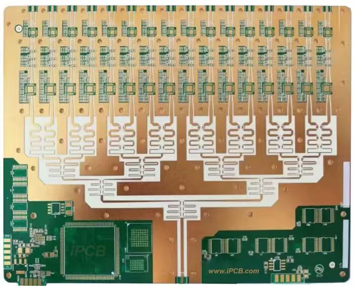
In the realm of printed circuit board (PCB) technology, not all boards are created equal. Among the most respected names in high-frequency and high-performance electronics is Rogers Corporation, whose engineered materials have become synonymous with consistent performance, reliability, and durability in demanding applications. Rogers PCBs refer to circuit boards manufactured using Rogers’ proprietary laminates, most notably PTFE-based (polytetrafluoroethylene) materials with ceramic fillers or other advanced dielectric formulations.
Unlike conventional FR-4 PCBs, which are widely used in consumer electronics, Rogers PCBs are designed to excel where signal integrity, minimal dielectric loss, and stable performance over a wide frequency and temperature range are critical. This makes them a go-to choice in fields such as:
RF (Radio Frequency) and Microwave Circuits for communication systems.
5G infrastructure components.
Radar and satellite communication equipment.
Automotive ADAS (Advanced Driver Assistance Systems).
High-speed digital applications where timing margins are tight and signal quality is paramount.
The growing demand for Rogers PCBs is driven by industries that cannot tolerate signal degradation, phase instability, or excessive heat buildup. These boards often sit at the heart of mission-critical systems — for example, the RF module in a commercial aircraft’s avionics or the transceiver in a 5G base station. In such environments, even a minor deviation in dielectric constant (Dk) can lead to significant performance issues.
Rogers PCBs
The core advantage of Rogers PCBs lies in their material science. Rogers laminates are engineered with precisely controlled dielectric properties. For example, popular materials like Rogers RO4003C and Rogers RO4350B are formulated to provide stable Dk values over broad frequency ranges and minimal dissipation factor (Df), ensuring that signal loss is kept to an absolute minimum.
Key performance characteristics include:
Stable Dielectric Constant (Dk) across temperature and frequency ranges.
Low Dissipation Factor (Df) for reduced signal attenuation.
Excellent Thermal Management, allowing for higher power handling.
Dimensional Stability, meaning that the board’s size and shape change very little under thermal cycling or humidity exposure.
This combination is essential in RF and microwave design because it directly impacts impedance control, signal transmission speed, and phase consistency — parameters that directly correlate to product performance and compliance with regulatory standards.
While these boards offer unparalleled performance benefits, they also carry a higher price tag than FR-4 boards. The cost difference is not arbitrary; it stems from:
Specialized raw materials that are inherently more expensive.
Complex fabrication processes requiring tighter tolerances and skilled operators.
Lower global supply availability compared to commodity FR-4.
Understanding what drives these costs is vital for engineers, procurement teams, and product managers. By identifying the primary cost components — from laminate selection to production yield — businesses can make informed decisions about when to invest in Rogers PCBs and how to optimize their budget without compromising performance.
When we talk about Rogers PCBs, we’re referring to more than just a high-performance printed circuit board — we’re talking about a material innovation that reshaped the way engineers design for high-frequency and high-reliability applications. To understand their current pricing dynamics, it’s important to look at how Rogers materials entered the market and evolved alongside industry demands.
Rogers Corporation was founded in 1832 — long before electronics even existed — as a paper manufacturer in Connecticut. Over the decades, the company transitioned into advanced materials, driven by the post–World War II electronics boom. By the mid-20th century, Rogers began experimenting with laminates made from PTFE (polytetrafluoroethylene), recognizing that its low dielectric constant and loss tangent could revolutionize RF circuit performance.
In the 1960s and 1970s, as satellite communication, radar systems, and military electronics surged in demand, Rogers developed specialized microwave circuit materials. These laminates offered consistent dielectric performance across wide frequency bands — something conventional phenolic or epoxy-based boards simply couldn’t achieve.
By the 1980s and 1990s, FR-4 was dominating the PCB world due to its low cost and good mechanical strength. However, engineers working on cellular base stations, high-speed telecom backplanes, and emerging satellite systems began to hit a wall:
FR-4’s dielectric constant wasn’t stable at high frequencies.
Losses became unacceptably high beyond a few gigahertz.
Temperature-related drift could compromise signal timing and integrity.
Rogers materials filled this gap. With controlled Dk values, lower signal loss, and thermal reliability, they became the go-to choice for telecom infrastructure and aerospace systems.
In the 2000s, the growth of consumer wireless devices, GPS navigation, and automotive radar pushed Rogers PCBs into new markets. Applications expanded into:
5G prototype systems long before the standard was finalized.
Automotive ADAS modules, where high-frequency radar is critical.
Medical imaging equipment like MRI systems.
The trend toward IoT devices with embedded antennas further reinforced the role of Rogers materials in miniaturized, high-performance designs.
Today, Rogers PCBs are at the heart of:
5G mmWave infrastructure — handling frequencies up to and beyond 77 GHz.
Low-Earth Orbit (LEO) satellites, where thermal cycling and radiation exposure demand superior stability.
Aerospace communication systems where mission failure is not an option.
What’s notable is that Rogers PCBs have moved from being a niche defense-sector product to a cross-industry standard for high-frequency applications. This broadened market means more production volume — but also more strain on the supply chain, which is one of the cost drivers we’ll discuss later.
The history of Rogers PCBs shows that their pricing is a reflection of specialized capability, not just brand premium. The long development cycle, stringent manufacturing requirements, and demand from multiple high-tech sectors all contribute to:
Higher baseline material costs.
Limited global production capacity.
Price sensitivity to supply chain disruptions.
These factors help explain why a procurement manager looking at FR-4 boards and Rogers PCBs will see such a large cost gap — and why that gap is often justified by performance requirements.
When engineers and procurement managers compare Rogers PCBs with conventional FR-4 boards, the most striking differences come from the base material properties. These are not just minor variations in composition — they are deliberate, highly engineered characteristics that define how the PCB behaves under electrical, thermal, and mechanical stress.
One of the most critical features of Rogers laminates is their tightly controlled dielectric constant. In RF and microwave applications, a stable Dk is vital because:
It determines the signal propagation speed through the PCB substrate.
Variations in Dk can cause impedance mismatches, leading to reflections and signal loss.
In phased-array systems, even small Dk fluctuations can create phase errors that degrade overall system performance.
For example, Rogers RO4003C has a nominal Dk of 3.38 ± 0.05 — a level of precision that is impossible to achieve with standard FR-4. This precision becomes especially valuable at frequencies above 10 GHz, where small inconsistencies can result in major performance drops.
The dissipation factor, sometimes called loss tangent, measures how much energy is lost as heat when a signal passes through the material. A lower Df means less attenuation over distance, which is essential for:
Long trace runs in RF circuits.
High-speed digital signals where eye diagram integrity matters.
Low-power wireless devices that need to maximize efficiency.
Typical FR-4 might have a Df of around 0.02 at 10 GHz, whereas Rogers materials can achieve values as low as 0.0017 — a more than tenfold improvement.
High-performance electronics often operate across wide temperature ranges — think of radar equipment in aircraft or telecom towers in desert conditions. Rogers laminates exhibit:
Minimal Dk variation over temperature changes.
Stable mechanical dimensions during thermal cycling.
Resistance to material softening or warping at elevated temperatures.
These qualities reduce the need for temperature-compensating circuit design, which simplifies engineering and lowers downstream manufacturing risks.
Moisture can be a hidden enemy in PCB performance, especially at high frequencies where water molecules can alter dielectric properties. Rogers laminates typically absorb far less moisture than FR-4, which helps maintain impedance stability even in humid environments.
Additionally, their low coefficient of thermal expansion (CTE) means they expand and contract predictably, which:
Improves reliability in multi-layer stackups.
Reduces stress on plated through-holes and vias.
Minimizes risk of delamination under thermal shock.
Rogers laminates are often paired with rolled annealed copper foil or specialized electrodeposited foils. The choice of copper affects surface roughness, which in turn influences high-frequency loss. Rolled copper foils offer smoother surfaces and better fatigue resistance, while electrolytic copper foils are more cost-effective for certain applications. (We’ll revisit this in the copper foil cost driver section.)
These advanced properties are not accidental — they come from precise material formulations, controlled manufacturing processes, and rigorous quality control. Each of these steps adds to the cost per panel:
The PTFE and ceramic fillers are more expensive raw materials.
Manufacturing lines require specialized lamination and drilling capabilities.
Yield rates must be high to justify production, which means tighter process controls and more frequent inspections.
In short, the performance benefits of Rogers PCBs are a direct result of these material advantages, and those advantages require more investment at every stage of production.
The decision to use Rogers PCBs is rarely about aesthetics or brand loyalty — it’s a strategic engineering choice rooted in the unique performance benefits they bring to critical applications. These advantages extend beyond pure electrical performance and touch on product reliability, long-term maintenance costs, and overall system efficiency.
At the heart of Rogers PCBs’ popularity is their ability to preserve signal quality over distance and across wide frequency ranges.
For RF and microwave applications, even slight signal degradation can mean the difference between compliance and failure.
In 5G mmWave systems, signal loss directly reduces transmission range and data throughput.
Rogers’ low Df ensures that energy loss is minimal, which improves both range and clarity.
This is particularly valuable in industries like telecommunications and aerospace, where clean signal transmission is a non-negotiable requirement.
Many modern devices operate in harsh conditions — high altitudes, desert heat, polar cold, or enclosed industrial machinery. Rogers PCBs maintain electrical stability and mechanical integrity under these extremes:
Minimal Dk drift ensures impedance stability in radar or satellite links.
High Tg (glass transition temperature) allows for better performance under sustained heat.
Lower thermal expansion reduces the risk of layer separation or via cracking.
This makes them a top choice in military electronics, outdoor telecom towers, and automotive radar systems.
Rogers PCBs are highly adaptable in terms of layer count, copper weight, and hybrid stackups (e.g., combining Rogers layers with FR-4 to balance cost and performance). This flexibility allows:
Mixed-signal designs with RF, analog, and digital sections.
Embedded antennas for IoT and communication devices.
High-density interconnects (HDI) with precise impedance control.
The ability to integrate multiple functions into a single, reliable board can reduce overall system size and weight, which is critical for aerospace and handheld devices.
Electronics that fail in the field can cost far more in repairs, recalls, or brand damage than the savings from using cheaper boards. Rogers PCBs deliver long operational lifespans thanks to:
Moisture resistance, preventing dielectric shifts in humid environments.
Low CTE, reducing mechanical stress on solder joints and vias.
Superior adhesion between copper and laminate, minimizing delamination risk.
This reliability is why Rogers PCBs are often found in mission-critical defense and aerospace systems where maintenance opportunities are rare or impossible.
For manufacturers in competitive industries, performance translates directly to market advantage. A faster, more reliable, and more compact device can win contracts and market share.
5G infrastructure providers can achieve better coverage with fewer towers.
Satellite manufacturers can meet weight and performance targets more easily.
Medical device makers can ensure consistent imaging or diagnostic results.
While Rogers PCBs may increase unit costs, they can reduce total cost of ownership by boosting efficiency, reducing warranty claims, and enhancing customer satisfaction.
When we later discuss cost drivers, these benefits will act as a reference point. In other words:
Yes, Rogers PCBs are more expensive to produce.
But their performance, reliability, and longevity often offset the initial premium.
For many applications, not using them would introduce risks or limitations that could be far more expensive in the long run.
One of the most significant factors affecting the price of Rogers PCBs is the raw material composition. Unlike conventional FR-4 boards, which rely primarily on epoxy resin and woven fiberglass, Rogers laminates use specialized polymers, ceramic fillers, and engineered adhesives to achieve their unique electrical and thermal properties.
Polytetrafluoroethylene (PTFE) is the backbone of many Rogers materials. Its properties — low dielectric constant, low dissipation factor, and excellent thermal stability — make it indispensable in high-frequency applications. However, PTFE is significantly more expensive than standard epoxy resins, both in raw material cost and in handling requirements during manufacturing:
PTFE is chemically inert and difficult to bond, requiring specialized processing equipment.
It cannot be cured in the same way as FR-4 resins; lamination processes are more intricate and time-consuming.
Waste management and scrap handling for PTFE materials also add to the overall cost.
To control the dielectric constant and improve thermal conductivity, Rogers laminates often include ceramic fillers. These additives ensure that Dk remains stable across temperature ranges, which is crucial for high-frequency RF signals.
High-purity ceramic powders are expensive and must be uniformly distributed in the polymer matrix.
The filler ratio must be precisely controlled; deviations can lead to off-spec boards that must be scrapped, increasing production costs.
Multi-layer Rogers PCBs rely on prepregs and adhesives that maintain adhesion without compromising electrical performance. These materials are formulated to:
Minimize signal loss at high frequencies.
Maintain dimensional stability under thermal cycling.
Resist moisture absorption.
Because these prepregs are custom-engineered, they are more costly than standard FR-4 prepregs.
The combination of PTFE, ceramic fillers, and specialty prepregs drives up the baseline material cost of Rogers PCBs. When procurement teams compare board quotes, material composition often accounts for 40–60% of total cost for high-frequency applications.
Understanding material composition is the first step toward cost optimization. Engineers can make informed choices about:
Layer count vs. performance requirements.
Hybrid stackups combining Rogers materials with lower-cost FR-4 in non-critical areas.
Copper foil selection, which we will cover in the next section.
Copper foil is one of the most critical components in PCB manufacturing, and its selection significantly influences both performance and cost of Rogers PCBs. The choice of foil affects signal integrity, thermal dissipation, mechanical stability, and ultimately, the board’s price.
Rolled copper foil is produced by mechanically rolling copper into thin sheets. This process creates a smooth surface finish that is ideal for high-frequency signal applications.
Advantages of Rolled Copper Foil in Rogers PCBs:
Low surface roughness: Reduces signal loss at microwave and RF frequencies.
Superior fatigue resistance: Better for flexible or multi-layer boards.
Enhanced adhesion: Works well with PTFE-based laminates due to consistent surface energy.
Cost Implications:
RCF is more expensive than electrolytic copper foil due to labor-intensive rolling and quality control processes.
Its superior performance is often justified in high-frequency applications, where FR-4 boards or rougher foils would result in signal degradation.
Electrolytic copper foil is produced via an electroplating process, which deposits copper onto a carrier sheet. It is more flexible and cost-effective than rolled foil, making it suitable for many standard PCB applications.
Advantages of Electrolytic Copper Foil:
Lower cost: Ideal for less critical signal paths.
High flexibility: Easier to handle during lamination.
Wider availability: Readily sourced from multiple suppliers.
Trade-Offs:
Higher surface roughness increases signal loss at high frequencies.
Reduced fatigue resistance compared to RCF.
Not ideal for Rogers PCBs in RF-critical applications.
The selection between RCF and ECF directly influences both material and production costs:
RCF increases baseline material costs due to premium copper prices and processing.
ECF can reduce cost, but may necessitate performance compromises, particularly at higher frequencies.
Design engineers often make strategic trade-offs:
Use RCF in RF-sensitive layers for high-frequency signal integrity.
Use ECF in inner layers or non-critical signal paths to lower overall cost.
This approach helps balance performance requirements with budget constraints, which is a recurring theme in Rogers PCB procurement strategies.
When evaluating quotes from manufacturers like JM PCB, it’s essential to confirm the type and quality of copper foil specified. Superior suppliers can:
Provide detailed datasheets showing foil roughness and conductivity.
Recommend hybrid foil strategies to optimize cost without sacrificing performance.
Ensure lamination and bonding processes are compatible with the selected foil type.
Choosing the correct foil type early in the design phase reduces the likelihood of rework or costly prototypes, which further impacts total project cost.
Beyond raw materials and copper foil, lamination and dielectric processing are among the most significant cost drivers for Rogers PCBs. These steps ensure the PCB achieves mechanical integrity, electrical performance, and thermal stability, but they also require specialized equipment, precision control, and skilled labor — all of which contribute to higher production costs.
Many Rogers PCBs are multi-layer boards, particularly in RF and high-speed digital applications. Layer count and lamination technique influence:
Adhesion quality between Rogers laminates and prepregs.
Dimensional stability across thermal cycles.
Yield rates, since misalignment or voids can render boards unusable.
Each additional layer adds both material and labor costs, because:
More layers require longer pressing times and higher lamination pressure.
Registration of layers must be precise to maintain signal integrity.
Rework or scrap due to lamination defects increases the effective cost per unit.
Rogers laminates, particularly PTFE-based ones, present unique challenges:
PTFE does not flow like epoxy resins during lamination, requiring specialized lamination cycles.
Dielectric fillers must remain uniformly dispersed, as variations can alter the dielectric constant (Dk) and dissipation factor (Df).
High-frequency applications demand tight Dk tolerance, which may necessitate additional quality checks and testing during processing.
The more stringent the dielectric specifications, the higher the process cost, since boards that fail testing or fall outside tolerance limits must be discarded or reworked.
Producing Rogers PCBs often requires:
Vacuum lamination presses to eliminate voids.
Controlled temperature and pressure profiles to prevent delamination.
Custom tooling for specific panel sizes or complex stackups.
These requirements translate into:
Higher capital investment for manufacturers.
Longer production cycles, as boards cannot be rushed without compromising quality.
Increased operational cost, especially for low-volume or prototype runs.
Lamination and dielectric processing can account for a significant portion of the final Rogers PCB cost, particularly for high-layer-count boards. Key cost influencers include:
Number of layers and prepregs.
Type and distribution of dielectric fillers.
Complexity of lamination tooling and press cycles.
Manufacturers like JM PCB often recommend design strategies to optimize lamination efficiency, such as:
Combining critical signal layers with Rogers materials while using FR-4 or other laminates for non-critical layers.
Designing stackups that minimize void formation and improve yield.
This approach helps control cost while maintaining the performance benefits of Rogers PCBs.
The layer count and design complexity of a PCB are closely tied to manufacturing difficulty, yield rates, and material usage. For Rogers PCBs, which are often used in high-frequency and high-performance applications, these factors play a particularly significant role in pricing.
High-frequency circuits often require multi-layer stackups to:
Separate signal layers from power and ground planes for optimal performance.
Provide shielding and impedance control to reduce noise and crosstalk.
Integrate complex routing for dense component placement.
Each additional layer increases:
Material costs: More Rogers laminates and prepregs are needed.
Lamination complexity: As explained in Section 7, multi-layer lamination requires precise registration and longer press cycles.
Drilling and plating efforts: More layers mean more via connections and potential for defects, affecting yield.
Modern high-speed designs often feature narrow traces and tight spacing, especially for RF and microwave circuits. Rogers PCBs support these requirements, but finer geometries come at a cost:
Advanced photolithography and etching processes are required.
Increased risk of defects like over-etching or short circuits.
Higher inspection and quality assurance needs.
The combination of fine pitch and multi-layer complexity directly increases processing time and labor costs, which contribute to the board’s price.
Complex designs often include blind or buried vias to connect inner layers without exposing them on the surface. While essential for high-density interconnects, these features require:
Precision drilling and plating.
Additional inspection and testing.
More sophisticated stackup planning to maintain signal integrity and impedance.
Blind and buried vias can significantly increase both material waste and production time, adding to overall cost.
Design complexity not only increases direct manufacturing costs but also affects yield rates:
Highly complex boards are more prone to manufacturing defects.
Defective boards must be scrapped or reworked, effectively increasing per-unit cost.
More advanced inspection techniques (AOI, X-ray, impedance testing) are needed to maintain quality standards.
Manufacturers like JM PCB often advise clients on design-for-manufacturability (DFM) strategies for Rogers PCBs:
Optimize layer count only where necessary.
Balance critical signal paths with simpler routing in non-critical areas.
Consider hybrid stackups combining Rogers and lower-cost laminates.
By carefully managing design complexity, it is possible to control costs without compromising performance, a crucial consideration for RF and high-speed digital applications.
In high-performance applications, Rogers PCBs often require extremely precise via holes and plating, especially when dealing with multi-layer boards, fine pitch components, or high-frequency signals. These manufacturing steps are critical for both electrical performance and mechanical reliability, but they also contribute significantly to overall production costs.
Rogers PCBs frequently use:
Microvias (less than 150 µm diameter) for high-density interconnects.
Blind or buried vias connecting inner layers without exposure on the board surface.
Precision drilling requirements include:
Laser drilling or high-speed mechanical drilling for accuracy and repeatability.
Tight positional tolerance to maintain layer alignment and impedance control.
Controlled copper smear removal to avoid short circuits or weak plating.
These steps are more time-consuming than standard via drilling and require specialized equipment, adding to production cost.
After drilling, vias must be copper-plated to create reliable electrical connections. In Rogers PCBs:
Copper plating must adhere to PTFE laminates, which are chemically inert and require surface treatment before plating.
Multi-layer boards often have through-hole, blind, and buried vias that demand uniform plating thickness.
High-frequency designs require controlled plating roughness to minimize signal loss.
The complexity of plating directly influences:
Production time.
Rejection rates due to uneven plating or voids.
Need for additional inspection methods, such as cross-section analysis or X-ray imaging.
Precision drilling and plating can account for 15–25% of the total manufacturing cost for complex Rogers PCBs. Factors include:
Number of vias: More vias increase drilling and plating time.
Via type: Blind and buried vias are more expensive than through-holes.
Inspection and testing requirements: Maintaining high yield rates adds labor and equipment costs.
Manufacturers like JM PCB often help clients optimize via design to reduce costs without sacrificing performance:
Combining microvias in high-frequency paths with standard vias in less critical areas.
Using optimized via dimensions to balance reliability and manufacturing feasibility.
Strategic placement of blind/buried vias to minimize lamination and drilling complexity.
Such approaches allow clients to achieve high performance while controlling overall Rogers PCB costs, particularly in multi-layer RF or high-speed digital designs.
Surface finish is a critical factor in Rogers PCB manufacturing because it affects solderability, signal integrity, and long-term reliability. The choice of surface finish can significantly impact both performance and overall production cost.
For Rogers PCBs, commonly used finishes include:
ENIG (Electroless Nickel Immersion Gold)
Provides excellent planarity for fine-pitch components.
Lowers oxidation of copper, improving long-term reliability.
Preferred for high-frequency applications due to stable signal performance.
OSP (Organic Solderability Preservative)
Cost-effective and environmentally friendly.
Suitable for less demanding applications.
Limited shelf life and less suitable for multi-layer high-frequency designs.
Immersion Silver (ImAg)
Provides low-resistance surfaces with good solderability.
Sensitive to sulfur contamination, requiring careful handling.
HASL (Hot Air Solder Leveling)
Traditional and inexpensive.
Not ideal for Rogers PCBs with fine-pitch or high-frequency circuits due to uneven surface profile.
High-frequency signals are sensitive to surface roughness and material interaction:
ENIG provides a smooth, consistent surface, minimizing signal loss.
HASL’s uneven profile can increase insertion loss and degrade high-speed signals.
Surface finish selection must align with copper type and design frequency requirements to ensure optimal performance.
Surface finish choice affects both direct material costs and processing costs:
ENIG is more expensive due to precious metal usage and multiple plating steps.
OSP and HASL are cheaper but may not meet high-frequency performance standards.
Selection of the optimal finish requires balancing performance needs against budget constraints.
To manage costs while maintaining performance:
Use ENIG for critical RF layers or fine-pitch components.
Consider OSP for non-critical inner layers where signal integrity is less demanding.
Work with experienced manufacturers like JM PCB, who can recommend the most cost-effective surface finish strategy for your specific application.
High-performance Rogers PCBs require rigorous testing and quality assurance (QA) to ensure that every board meets electrical, thermal, and mechanical specifications. Testing is a major cost driver because it involves specialized equipment, labor, and sometimes destructive analysis.
Electrical testing ensures the PCB functions according to design specifications:
Impedance testing verifies that signal paths maintain precise resistance, capacitance, and inductance values.
Continuity and isolation testing checks for shorts, opens, or leakage between conductors.
High-frequency signal testing evaluates insertion loss and return loss in RF paths.
Electrical testing is particularly critical for Rogers PCBs because signal integrity is sensitive to material properties, copper foil, and via quality. Complex boards may require layer-by-layer testing, which increases time and labor costs.
Rogers PCBs often operate in harsh environments, so mechanical and thermal reliability is essential:
Thermal cycling tests the board’s ability to withstand temperature changes without delamination or via failure.
Mechanical stress tests evaluate bending, vibration, and flex resistance, especially for multilayer and flexible Rogers PCBs.
These tests require specialized chambers and equipment, adding both operational and capital costs to the PCB production process.
Advanced inspection ensures manufacturing defects are minimized:
Automated Optical Inspection (AOI) detects surface defects and trace anomalies.
X-ray inspection identifies hidden issues in blind or buried vias.
Cross-section analysis verifies layer adhesion, via plating, and lamination quality.
Inspection costs increase with board complexity and layer count, and rework or scrap resulting from failed inspections further affects overall pricing.
Testing and QA can account for 10–20% of total Rogers PCB cost, depending on board complexity and performance requirements:
High-frequency, multi-layer boards require more extensive testing.
Boards destined for aerospace, defense, or medical applications demand stricter QA standards.
Experienced manufacturers like JM PCB can optimize testing protocols to balance reliability and cost, helping clients reduce unnecessary overhead without compromising performance.
Rogers PCBs are premium high-performance boards designed for demanding applications in RF, microwave, aerospace, defense, and high-speed digital systems. Their advantages — including superior signal integrity, thermal stability, mechanical reliability, and long-term durability — make them indispensable in modern electronics, despite their higher upfront costs compared to standard FR-4 boards.
Material Selection Drives Cost
PTFE-based laminates, ceramic fillers, and specialty prepregs form the core of Rogers PCBs, accounting for a significant portion of total cost.
Strategic choices, such as hybrid stackups or selective use of rolled vs. electrolytic copper foil, can balance performance and budget.
Design Complexity Matters
Multi-layer boards with microvias, blind/buried vias, and fine traces enhance functionality but increase manufacturing complexity, inspection requirements, and yield risks.
Optimizing layer count, trace routing, and via placement is essential for cost control.
Processing and Surface Finishes Affect Pricing
Lamination, dielectric processing, precision drilling, and plating all add labor, equipment, and operational costs.
Surface finishes like ENIG enhance high-frequency performance but increase expenses; selective use of OSP or HASL can reduce costs.
Testing and Quality Assurance Ensure Reliability
Rigorous electrical, mechanical, and thermal testing is crucial for mission-critical applications.
Experienced manufacturers like JM PCB can help optimize QA processes to reduce unnecessary costs while ensuring high reliability.
By combining informed material choices, thoughtful design planning, optimized surface finishes, and strategic testing, engineers and procurement teams can achieve high-performance Rogers PCBs without excessive cost overruns. Partnering with knowledgeable suppliers like JM PCB provides technical guidance and process optimization, ensuring that the final boards meet both performance requirements and budget constraints.
While the upfront investment in Rogers PCBs may be higher, their superior electrical performance, reliability, and long-term durability often justify the cost, especially in high-frequency, high-performance, and mission-critical applications. Understanding the key cost drivers and implementing strategic optimizations ensures that engineers and companies can leverage the full potential of Rogers PCBs while managing expenses effectively.
Rolled copper foil (RCF) is produced by mechanically rolling copper into thin sheets, offering better surface quality, fatigue resistance, and adhesion, ideal for high-frequency applications.
Electrolytic copper foil (ECF) is deposited via an electrolytic process, making it more flexible and cost-effective, suitable for non-critical inner layers.
Higher layer counts increase material usage, lamination complexity, and drilling/plating operations, all of which raise production costs.
Multi-layer designs require precise registration and quality checks, making complexity a major cost driver.
ENIG (Electroless Nickel Immersion Gold) provides a smooth, oxidation-resistant surface ideal for fine-pitch components and high-frequency signal paths.
Although more expensive than OSP or HASL, ENIG ensures signal integrity and long-term reliability, especially in critical RF applications.
Complex designs with microvias, blind/buried vias, and fine traces are more prone to defects such as misregistration, over-etching, or plating failures.
Lower yield due to defects increases per-unit cost, emphasizing the importance of design-for-manufacturability (DFM) practices.
Material composition (PTFE laminates, ceramic fillers, prepregs) is the largest contributor.
Layer count and design complexity, including via types and routing, influence processing costs.
Surface finish, copper foil type, and QA/testing add additional cost layers.


Connect to a Jerico Multilayer PCB engineer to support your project!
Request A Quote


 Quote
Quote