


+86 13603063656
The electronics industry is constantly evolving toward smaller, lighter, and more durable products. Devices such as smartphones, wearable technologies, automotive electronics, and aerospace systems all demand circuit boards that can bend and adapt to three-dimensional designs while maintaining long-term reliability. Flexible printed circuit boards (flex PCBs) are widely used to meet these needs, but flexibility can sometimes compromise mechanical stability and assembly reliability. This is where the Stiffener Flex PCB plays an indispensable role.
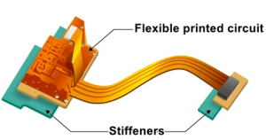
A Stiffener Flex PCB is not simply another variety of PCB; rather, it is a specialized design that incorporates stiffeners into specific areas of a flexible circuit to enhance rigidity, protect delicate components, and improve overall manufacturability. By balancing flexibility with localized structural reinforcement, stiffeners allow designers to optimize performance without sacrificing durability.
From my perspective, the adoption of stiffeners is not just a technical necessity—it represents a design philosophy. Engineers must carefully evaluate where rigidity is essential and where flexibility must be preserved. This balance directly influences yield rates in production, device longevity, and ultimately, user satisfaction.
Stiffener Flex PCB
A Stiffener Flex PCB integrates stiffening materials—such as polyimide, FR-4, or stainless steel—into targeted zones of a flexible PCB. These stiffeners are laminated or bonded to the flex substrate, creating hybrid areas of stiffness and flexibility.
Key characteristics of Stiffener Flex PCB include:
Localized Rigidity: Reinforcing regions where connectors, components, or solder joints are located.
Enhanced Assembly Support: Preventing flex damage during surface mount technology (SMT) or through-hole soldering processes.
Thermal Dissipation: Some stiffeners, especially metallic ones, improve heat distribution.
Dimensional Stability: Providing flatness for pick-and-place equipment during high-speed assembly.
From a manufacturing standpoint, the stiffener is not considered an electrical layer; rather, it is a mechanical enhancement. This makes the Stiffener Flex PCB a bridge between electrical functionality and structural reliability.
The Stiffener Flex PCB is widely valued because it enhances the usability and robustness of flexible circuits. Some of the main advantages include:
Improved Component Mounting Reliability
SMT components require a stable platform for soldering. Without stiffeners, excessive bending could lead to solder joint cracks.
Connector Reinforcement
Connectors are often subject to repeated plugging and unplugging, creating mechanical stress. A stiffened region distributes force and reduces stress concentration.
Better Heat Dissipation
Using metal stiffeners helps conduct heat away from power components, extending product lifespan.
Enhanced Flatness During Assembly
Automated pick-and-place machines demand flat surfaces. The Stiffener Flex PCB provides the required planarity.
Protection Against Mechanical Wear
By stiffening bend-restricted zones, designers prevent long-term damage due to repeated mechanical stress.
In my own reflection, I believe the biggest benefit lies in design flexibility itself. Engineers can selectively decide where strength is needed, without sacrificing the inherent advantages of flexible circuits. This fine-tuned approach improves both manufacturing efficiency and end-user reliability.
The practical use cases of Stiffener Flex PCB span multiple high-demand industries:
Consumer Electronics: Smartphones, laptops, and cameras integrate stiffeners in connector zones to ensure durability.
Automotive Electronics: Vehicles employ flex PCBs with stiffeners in infotainment systems, ADAS modules, and dashboard electronics.
Aerospace and Defense: Reliability is paramount, and stiffeners ensure circuits withstand vibration, shock, and thermal cycling.
Medical Devices: Miniaturized diagnostic equipment uses stiffened circuits to maintain assembly stability under frequent use.
Wearable Technology: Smartwatches and fitness trackers require a mix of flexibility and structural support.
Designing and manufacturing a Stiffener Flex PCB requires attention to multiple engineering factors:
Material Selection: Polyimide for flexibility, FR-4 for rigidity, and metals for thermal/structural needs.
Adhesive Choices: Pressure-sensitive adhesives (PSA) or thermosetting adhesives determine durability.
Alignment Accuracy: Stiffener placement must align perfectly with PCB zones to ensure assembly compatibility.
Thickness Control: The combined thickness of the flex plus stiffener must meet connector or housing tolerances.
Cost vs. Performance Trade-off: Thicker stiffeners provide stability but increase overall cost and reduce flexibility.
Designing a Stiffener Flex PCB is not just about attaching a rigid backing to a flexible substrate. Instead, it is a process that requires careful trade-offs between mechanical reinforcement and electrical performance. Engineers must optimize design parameters to ensure that stiffeners serve their purpose without introducing new problems.
The first step in optimizing a Stiffener Flex PCB is deciding where to place stiffeners. Generally, they are positioned:
Under components that require stable soldering platforms.
At connector interfaces to minimize mechanical stress.
In zones where the PCB must be clamped during assembly.
Placing stiffeners arbitrarily may lead to uneven stress distribution, warpage, or difficulties during the lamination process.
The thickness of the stiffener plays a crucial role in balancing rigidity with flexibility. For example:
Thin stiffeners (0.1–0.3 mm) are ideal for consumer electronics where compactness is critical.
Medium stiffeners (0.4–0.8 mm) are widely used in automotive and industrial devices.
Thicker stiffeners (>1 mm) are employed in aerospace and defense systems that demand maximum durability.
The adhesive layer used to bond the stiffener to the flex substrate directly impacts thermal and mechanical reliability. High-performance adhesives ensure long-term durability even under thermal cycling and vibration. Engineers must also consider outgassing, which can cause defects during reflow soldering.
A Stiffener Flex PCB must be designed with downstream assembly processes in mind. For example:
In SMT assembly, stiffeners should prevent board warpage during reflow.
In through-hole processes, stiffeners may need cutouts for lead insertion.
For automated assembly lines, precise dimensional control is mandatory.
In my opinion, design optimization is where engineering creativity truly shines. The stiffener is not an afterthought—it must be integrated into the design philosophy from the very beginning.
Since stiffeners serve as a structural backbone, their reliability must be validated through rigorous testing. A poorly engineered Stiffener Flex PCB can cause catastrophic failures in high-value devices.
The PCB is subjected to alternating hot and cold environments to simulate real-world usage. Stiffener bonding integrity and solder joint reliability are closely monitored.
Automotive, aerospace, and military applications require Stiffener Flex PCB designs to endure strong vibrations and sudden impacts without delamination.
Even though stiffened regions are not meant to bend, the overall circuit must withstand repeated flexing cycles. Engineers measure crack formation, adhesive failure, and electrical continuity.
Moisture resistance, salt spray exposure, and chemical resistance tests ensure the stiffener bond holds under adverse environments.
Non-destructive inspection methods like X-ray analysis are used to detect voids, misalignment, or insufficient adhesion in stiffener bonding.
From my perspective, reliability testing is not just a checkbox requirement; it is a design feedback loop. Each failure mode teaches us something about material compatibility, process refinement, or assembly constraints.
Even though Stiffener Flex PCB technology is well established, engineers and manufacturers face certain recurring challenges.
Challenge: Poor bonding between stiffener and flex substrate.
Solution: Use high-quality adhesives, apply correct lamination pressure, and maintain clean surfaces before bonding.
Challenge: Uneven thickness or stiffener misalignment can cause warping.
Solution: Symmetrical stiffener placement and precise lamination temperature control.
Challenge: Incorrect stiffener placement may compromise the overall bendability of the flex PCB.
Solution: Careful mechanical simulation during design to ensure flexible zones remain unaffected.
Challenge: Stiffener integration raises production cost compared to standard flex PCBs.
Solution: Optimize stiffener thickness and material selection. Collaborating with experienced manufacturers like JM PCB can reduce overall costs through efficient processes.
Challenge: Non-uniform thickness complicates robotic pick-and-place operations.
Solution: Use panelization and support tooling during SMT assembly.
The role of Stiffener Flex PCB will only grow as electronics continue to demand higher integration, lighter weight, and improved durability. Several future trends are worth highlighting:
Integration with Advanced Materials
Future stiffeners may use carbon-fiber composites or nano-enhanced polymers for ultra-lightweight strength.
Thermal-Functional Stiffeners
Stiffeners may not only provide mechanical support but also act as heat spreaders and EMI shields.
Miniaturization-Friendly Designs
With wearable technology driving ultra-thin designs, stiffeners will evolve toward micro-lamination techniques.
Sustainability in Materials
Eco-friendly stiffener materials that are recyclable or bio-based will gain traction as industries push for green electronics.
AI-Assisted Stiffener Design
Using AI simulation, designers may automatically optimize stiffener placement for maximum yield and reliability.
In my personal reflection, I see the Stiffener Flex PCB as more than just a mechanical reinforcement—it is evolving into a multifunctional element that combines mechanical, thermal, and even environmental performance.
Understanding the difference between flexible PCBs with and without stiffeners highlights why Stiffener Flex PCB has become a critical design choice.
Without Stiffeners:
Flexible PCBs without stiffeners rely solely on the substrate for support. This can lead to excessive bending in high-stress areas, solder joint cracking, and connector fatigue. Long-term usage often results in premature failure, especially in consumer electronics and automotive applications.
With Stiffeners:
Stiffeners localize rigidity where it is most needed, protecting components and connectors from mechanical stress. This ensures that solder joints maintain integrity and reduces the likelihood of failure during repeated bending or vibration.
Without Stiffeners:
Heat dissipation relies only on the flexible substrate, which has limited thermal conductivity. Hot spots may form under power components, leading to potential thermal degradation.
With Stiffeners:
Metallic stiffeners act as heat spreaders, distributing thermal energy away from critical zones. This reduces localized overheating and prolongs the operational life of sensitive components.
Without Stiffeners:
Warping or bending during SMT and through-hole assembly can result in misalignment, defective solder joints, or rejected boards.
With Stiffeners:
Stiffened areas provide a flat and stable platform for assembly, improving pick-and-place accuracy, reflow soldering reliability, and overall yield.
Without Stiffeners:
Flexible PCBs without reinforcement are more vulnerable to vibration, shock, and thermal cycling. Moisture ingress or mechanical fatigue can lead to early failures.
With Stiffeners:
Stiffeners enhance dimensional stability, ensuring that PCBs withstand environmental stress over long periods. This is particularly critical in automotive, aerospace, and medical devices.
Conclusion: The evidence is clear—integrating stiffeners into flexible PCBs is not just a design preference but a reliability-driven necessity. The trade-off in added cost is offset by improved performance, yield, and product longevity.
High-quality Stiffener Flex PCB production requires precision at every stage. Key strategies include:
Ensuring accurate placement of stiffeners is critical. Misalignment can cause connector interference, warping, or uneven stress distribution. Automated optical inspection and laser-guided placement systems are commonly used.
Pressure and temperature are carefully monitored during lamination to avoid adhesive voids or delamination.
Curing profiles are optimized based on material type (polyimide, FR-4, metal).
Thermosetting adhesives offer superior long-term bonding but require higher processing temperatures.
Pressure-sensitive adhesives (PSAs) are easier to process but may degrade under thermal cycling.
Material compatibility and environmental conditions must guide adhesive choice.
X-ray, cross-sectioning, and optical inspection ensure proper bonding and absence of defects.
Warpage measurements and flatness tests verify that stiffened zones meet assembly requirements.
Manufacturers like JM PCB employ rigorous quality control and continuous process refinement to reduce defect rates and ensure repeatable results, particularly for high-reliability applications.
After exploring design principles, advantages, applications, manufacturing processes, and industry case studies, several key points emerge:
Structural Support is Critical: Stiffeners provide localized rigidity, protecting components and connectors from mechanical and thermal stress.
Design Optimization Matters: Correct placement, thickness selection, and adhesive choice ensure that flexibility and reliability are balanced.
Industry Applications are Wide-Ranging: Consumer electronics, automotive, aerospace, medical devices, and wearables all benefit from Stiffener Flex PCB solutions.
Material Science Drives Performance: Polyimide, FR-4, metal, and composite stiffeners offer different trade-offs in weight, rigidity, and thermal properties.
Manufacturing Quality Ensures Reliability: Precision alignment, controlled lamination, and rigorous inspection are essential for high-yield, high-reliability production.
Future Trends Include Multi-Functional Stiffeners: Thermal management, EMI shielding, AI-assisted design, and sustainable materials will shape next-generation stiffener technologies.
1. What is the difference between rolled copper foil and electrolytic copper foil?
Rolled copper foil is produced by mechanically rolling copper into thin sheets, offering better surface quality and mechanical strength. Electrolytic copper foil is deposited via an electrolytic process and is more flexible and cost-effective.
2. Why are stiffeners used in flexible PCBs?
Stiffeners provide localized rigidity, ensuring component stability, connector reliability, and improved thermal management.
3. What materials are commonly used in Stiffener Flex PCB?
Common materials include polyimide, FR-4 fiberglass, stainless steel, and aluminum. Each offers different mechanical and thermal benefits.
4. Can stiffeners affect the flexibility of the overall circuit?
Yes. Stiffeners reduce flexibility in specific regions, but they are applied strategically so that the circuit retains bendability where needed.
5. How do stiffeners improve soldering reliability?
By flattening and stabilizing regions where components are mounted, stiffeners prevent stress on solder joints and improve assembly yield rates.


Connect to a Jerico Multilayer PCB engineer to support your project!
Request A Quote


 Quote
Quote